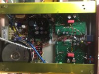
I have wanted to build the EL84 version for a while and scrounged up all the parts needed to do it while we are in lockdown here. The chassis is made out of bits and pieces of chassis and scrap. The HV transformer is a 300w 120/240v adapter toroid so it’s much bigger than needed. I used 2 low voltage transformers, 1 for the +20v driver power and +12.6v for the 12ax7 and a second winding for the -36v bias voltage. A centre tapped transformer supplies 2 x 6.3vac for the power tubes.
I have regulated 12.6v 12ax7 filament,-36 for the bias and +295 for the B+. I used the Power supply board and modified it extensively to produce the regulated voltages I needed. I also re configured the relay to use the normally closed contacts to hold the HV to 100v for The delay time which I set to 1 minute. For output transformers I used the Toroidy 8k UL transformer which I have had since ordering them along with the EL34 outputs for that BH version. These are also quite large, being rated at 40w.
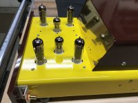
Fitting all this in the chassis became a big job. I was also concerned about hum issues with AC on the power tube filaments and 3 transformers in the mix.
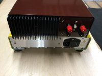
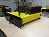
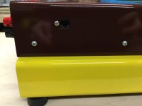
Oh! And I painted it yellow and brown. Looking through my paint supply I found black but wanted something brighter, to lift the mood during these stressful times.
I ended up attaching the RCA connectors to the front sides of the chassis rather than the top, where I have seen it done before. I always thought it would be awkward and in the way to have the cables coming into the top of the chassis so I tried something different.
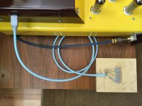
Bias adjustment was another issue. I did not have room to mount a switch and meter like on the EL34. So I came up with using the 8 pin RJ45 internet connector to bring up to 8 wires to the side of the top cover. I then connect a network cable with the other end connected to a terminal strip and can easily measure the low voltage bias voltages. I still have 2 wires of 8 which could be used to monitor a divided down HV and -bias voltage. I will post again about the tubes and operating points etc used.
I have regulated 12.6v 12ax7 filament,-36 for the bias and +295 for the B+. I used the Power supply board and modified it extensively to produce the regulated voltages I needed. I also re configured the relay to use the normally closed contacts to hold the HV to 100v for The delay time which I set to 1 minute. For output transformers I used the Toroidy 8k UL transformer which I have had since ordering them along with the EL34 outputs for that BH version. These are also quite large, being rated at 40w.
Fitting all this in the chassis became a big job. I was also concerned about hum issues with AC on the power tube filaments and 3 transformers in the mix.
Oh! And I painted it yellow and brown. Looking through my paint supply I found black but wanted something brighter, to lift the mood during these stressful times.
I ended up attaching the RCA connectors to the front sides of the chassis rather than the top, where I have seen it done before. I always thought it would be awkward and in the way to have the cables coming into the top of the chassis so I tried something different.
Bias adjustment was another issue. I did not have room to mount a switch and meter like on the EL34. So I came up with using the 8 pin RJ45 internet connector to bring up to 8 wires to the side of the top cover. I then connect a network cable with the other end connected to a terminal strip and can easily measure the low voltage bias voltages. I still have 2 wires of 8 which could be used to monitor a divided down HV and -bias voltage. I will post again about the tubes and operating points etc used.
Attachments
-
 5EFC1AEA-44EA-48A0-9BE6-816D63EDCDAB.jpeg323.1 KB · Views: 475
 -
 FC07FA2F-9613-4ECC-BCA0-259B0DCA19F3.jpeg231.5 KB · Views: 481
 -
 4E99EC67-D1DA-4B79-BA0E-4BE193F9FA3C.jpeg233.9 KB · Views: 479
 -
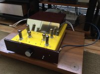 image.jpg766.9 KB · Views: 464
 -
 015A306A-EDEA-4EB5-A8DF-EE5F600AF209.jpeg187.2 KB · Views: 473
 -
 4DC926C5-C7D7-4792-B058-B5B7A5C0C17C.jpeg286.5 KB · Views: 223
 -
 634F799B-8B16-4CB6-A3A7-B936B72A48C5.jpeg233.9 KB · Views: 240
Last edited:
I have built this amp as an integrated amplifier with a 50k Alps blue volume control and a 3 position switch that allows 2 levels of HP filtering and a straight through connection. I normally use sub woofers in my setup so thought that with only 10W on tap it would be useful to have a HP filter to make the most of the power available.
The amp has a 4/8 ohm switch located between the speaker posts on the rear panel. Power switch is on the rear of the right side. The line entry module has a fuse and line filter. I also have a B+ fuse internally for the primary of the 240v transformer.
The HV regulator is mounted on the heatsink at the rear of the top section where the output transformers are mounted. Attached is a photo of the bias adjustment cable and terminal strip. This works well.
Tubes- I have a pair of EH 12ax7 in the front end and 6P15P-EV for output tubes. I have some used El84 from guitar amps but many of them are noisy. I only have one good pair so I was able to test with them only.
The 6P15P puts out nearly identical power to the EL84 but needs a bit less drive voltage so sensitivity is a bit higher. Operating point is 30ma, limited by the screen dissipation limit. With EL84 you can easily run 35 ma for more class A power but peak output remains almost identical. About 11watts at 3% thd. Output impedance running without global feedback measured slightly lower with the 6P15P at just over 2 ohms on the 8 ohm tap. The Toroidy output transformers have very low internal series resistance which helps to lower output impedance. They also have wide bandwidth, a slight peak in the response of a DB or so at 140khz and -3db somewhere in the 200khz range. Impressive transformer performance!
Attachments
Last edited:
Great looks and unique build. Congratulations, Brian. I have a couple questions for you, but first how do the amps sound? How do they (within power level differences) compare with your KT88 BH? Hope you enjoy the little brother as well.
1. Are you using the UL arrangement with your 6P15P outputs? Value of your UL/screen resistors? The real question is: how do you determine that you need to run 30ma per tube to keep the screen dissipation within limits? Do you have evidence that those limits must be observed at the risk of running the screens into trouble?
2. What are the operating conditions of your 12ax7 tubes? What is the value of your R18 resistor and voltage across it?
Hello Francois. On my speakers and in my system I prefer the sound of this amp over the KT88 version, which I am going to be putting back on the test bench in the future to make some improvements. The kt88 version always sounds thin in the upper midrange. I had put it down to the output impedance interacting with the fairly difficult load, but now I think that is not the issue.
Using UL output stage. I am using 1k for the screen resistors. I first ran the amp boards in a mock up of the amp built on a workbench and a piece of plywood to mount the amp and ps boards. Being unfamiliar with 6p15 operating points I was monitoring screen currents via the voltage drop across the 1k resistors. At a 295 HV and with the low resistance primary of the Toroidy transformer dropping very little voltage a cathode current of 35 ma had screen currents approaching 6ma. That is getting close to the 1.5watt limit. I am not sure how far you can push these tubes. They are very sturdy, noticeably heavier than the 6BQ5/el84s I had on hand. Decware uses these tubes a lot and in their DIY 2w SE tried amp they run them at 25ma and over 350v. That is triode wired.
When I tested EL84s I could run them at 35 ma without getting too close to the 2w screen limit. Generally I think it is good practice to run tubes within the max recommenced ratings unless you have hard proof that it is not going to cause premature failure when exceeding the limits. What will happen at the speaker output if a screen grid melts down? I’m not sure so I will proceed with caution.
I adjusted R18 on the fly during testing. I found that higher 12ax7 plate currents gave lower distortion and higher gain.I lowered the plate resistors from 220k to 180k and r16 from 15k to 10k to increase the LED current slightly given that I was using only -36volts for bias. I started with 820 ohm for R18 and then paralleled resistors to get where I felt was best.I settled on a plate voltage of 120v which may sound low but in my measurements this yielded lower distortion. Your mileage may vary.
Voltage across R18 should always be the LED voltage- the transistor Vbe or typically 1.8v-.65v=1.1-1.2 volts.
The 6P15 has very low microphonic, perhaps because of the military build quality and they sound quick and tight. I started with the ports plugged on my monitor audio 300gold speakers, with the belief that the overall higher bass impedance of the sealed box would be a good thing. Bass was a bit undefined. With the port plugs removed, bass was much better, excellent in fact. The overall tonal balance is full, images are full width and go deep, and the highs are all there. It does not sound strained or obviously coloured even when driving a pretty demanding load. It plays loud enough for nearly all my listening, and is particularly good on jazz or blues recordings. Low bass notes are not an issue, Distortion at 30hz is not much more than 1khz with the toroid output transformers.
I did make a few more changes to the circuit but I need to go now.
I adjusted R18 on the fly during testing. I found that higher 12ax7 plate currents gave lower distortion and higher gain.
...omissis...
I settled on a plate voltage of 120v which may sound low but in my measurements this yielded lower distortion. Your mileage may vary.
Voltage across R18 should always be the LED voltage- the transistor Vbe or typically 1.8v-.65v=1.1-1.2 volts.
I was talking about it in another thread:
So, considering that 0,6 mA on the 267k loadline will make the triode working approximately at -1,5V, I would ask if other dc loadlines has been tested, EG:
- 100k 47k 16k (147k loadline, needs 1 mA to work at -1,5V considering 320V for the EL84s)
From 12ax7 datasheets ( http://tdsl.duncanamps.com/pdf/vm345.pdf ) it seems to have 10% less distortion at 1 mA than 0,6 mA.
Have you tried something like this? Seems to have a similar working point as the original schematic, but more current so indeed less distortion (10% looking art the plots in the datasheet) and a higher mu, a lower internal resistance and an higher S.
Thanks in advance
Roberto
We need to remember that when using data sheet curves to draw load lines we are adding a simple resistive load. In the Baby Huey circuit there is shunt feedback at play, which means that the results are different than with a simple resistor. You could test the driver stage without the output tubes in the circuit and tune it for minimum distortion, but when the tubes are installed the input from the shunt feedback will alter the results. The input stage is also a differential amplifier with a current source in the cathode so it is not the same situation at all as drawing a load line on a set of curves. I measured the driver stage only before installing the output tubes and got distortion figures at the source follower output of roughly .1% for 10vpeak output, which seemed very low to me. I did not have time to try every combination of plate resistor, feedback resistor etc. Later with the output tubes installed I observed lower overall amplifier distortion when increasing plate current so I did so until I came to as low as I wanted to go with the plate voltage.
Build it and tweak it to your hearts content. If you can measure the distortion in circuit that will be so much more informative than a load line based estimate. Tubes are all different as well. That is one of the benefits that is being chased when feedback is used. It makes the end result more consistent if you are mass producing product.
Build it and tweak it to your hearts content. If you can measure the distortion in circuit that will be so much more informative than a load line based estimate. Tubes are all different as well. That is one of the benefits that is being chased when feedback is used. It makes the end result more consistent if you are mass producing product.
- Home
- Amplifiers
- Tubes / Valves
- Pandemic lockdown build- Yet one more Baby Huey EL84 -