Hi,
I am trying to understand the components in the Yamaha CA610II circuit diagram attached and how they affect the headphone output impedance
My goal is to insert a switch to change the output impedance depending on the headphone I am using.
I’d also like to know how to calculate the output impedance from the headphone out from the circuit diagram!
Thanks
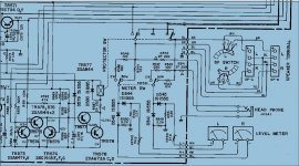
It will be about 220 ohms. This is because a 220ohms resistor is placed in series with the output from the speaker o/p point, and that has presumably a very low output impedance.
To change it just change the pair of 220 resistors R541/542.
To change it just change the pair of 220 resistors R541/542.
220 ohm.
If you really want to get the most out of your headphones forget about driving them with a power amp, build a dedicated headphone amp with the correct amount of gain (and low output impedance).
If you really want to get the most out of your headphones forget about driving them with a power amp, build a dedicated headphone amp with the correct amount of gain (and low output impedance).
Thanks gents.
Curious why dropping the impedance and using the power amp is inferior to a dedicated HP amp?
I believe AKG701 and senn HD6XX work well with 120ohm output impedance?
Curious why dropping the impedance and using the power amp is inferior to a dedicated HP amp?
I believe AKG701 and senn HD6XX work well with 120ohm output impedance?
A dedicated headphone amp would have a low impedance output and so not allow variations in headphone driver impedance to affect the response and damping. The resistor method is the time honoured (cheap) way of doing it. You could use lower value resistors (calculate the wattage needed) and use a switchable shunt resistor to alter level. That would lower impedance considerably.
(Silly analogy... the resistive feed method is like making a power amplifier with a 1000 or 10,000 volt output capability and coupling it to speakers via a 1k resistor)
(Silly analogy... the resistive feed method is like making a power amplifier with a 1000 or 10,000 volt output capability and coupling it to speakers via a 1k resistor)
No need for a dedicated headphone amp, just use a step down transformer. This will give both low output impedance and allow much more of a usable volume control range from your existing amp.
No need for a dedicated headphone amp, just use a step down transformer. This will give both low output impedance and allow much more of a usable volume control range from your existing amp.
Thanks mooly. How do I calculate the wattage needed for lower value resistor?
Take the wattage of the amp, say 50 watt rms and calculate the worst case scenario.
50 wrms is 20 volts rms (assuming an 8 ohm specified amp) and as W=V squared/R so then V = squareroot of 8 * 50.
Take your lower resistor value, say 100 ohm and calculate the total current with no headphone attached (that's the worst case) which is R=220 + 100 giving 330 ohms total. I =V/R which is 20/330 and so the current is 0.06 amps.
W=I squared times R and so the resistor needs to be able to handle 0.36 watt rms.
That's worst case for a 50 wrms amp delivering a voltage of 20 volts rms to the resistor network. So in practice a 0.5 or watt would be fine.
Edited... a wrong value crept in there somewhere 😉 The hazards of the Windows calculator.
Thanks again Mooly. I'm just wondering if I could remove the resistors and solder wire in there place. Keeping the volume low should be OK for the headphones?
Personally I wouldn't be all that happy with that approach because there is always the danger of someone plugging another set of 'phones in.
There is actually another very good reason not to do that... the amplifier output may well sound pretty noisy fed direct to 'phones because there is no attenuating effect of the resistor.
There is actually another very good reason not to do that... the amplifier output may well sound pretty noisy fed direct to 'phones because there is no attenuating effect of the resistor.
A mistake could mean the headphones survive just long enough to damage your ears.
Most headphones are designed to run from a resistive source. You could lower the resistor value if you have low impedance phones but I would not go too low. Better to use a proper headphone amp.
Most headphones are designed to run from a resistive source. You could lower the resistor value if you have low impedance phones but I would not go too low. Better to use a proper headphone amp.
Good points. I'll play it safe and keep the resistance over 40ohms for now. I just opened it up and noticed the resistors have that woven cloth sleave over them. Is that protect against heat?
It will be some safety regulation. The woven material will probably make the resistor 'flame proof' should a fault occur putting rail voltage across the resistor, or should a customer try and apply 240 volt mains to the headphone socket... don't laugh... much more bizarre things than that happen.
The cloth sleeve is there to protect other components.
If you want a lower impedance using your power amp, and given that the 220R gives the right volume, I would....
Measure or find out from the headphone spec what it's impedance is.
Use a 1 watt resistor (x2 for L&R of course) in parallel with the headphones of roughly half that value.
Have a series resistor of adequate wattage that gives a good volume setting similar to the standard 220R's volume. Probably 50R or so so you'll need a 10w power resistor.
This way your headphones will see an effective output impedance of the 2 resistors in parallel (even though they're not physically in parallel) and will be low enough to give some electrical damping that you don't get with 220R. If it sounds better then it was worth doing.
- Status
- Not open for further replies.
- Home
- Amplifiers
- Solid State
- Output impedance of Yamaha CA610ii headphone jack