There is no PWM or anything related present on the board vias of the driver board.
Also when installing the driver board there is no PWM measurable on the pins
Also when installing the driver board there is no PWM measurable on the pins
Attachments
Last edited:
Thanks for the response 🙂
I found out this amplifier needs a music signal to create an output PWM.
When there is no music signal, it doesn't PWM switch the output fets.
Even when the amplifier is turned on with a 50Hz sine wave, it stops creating an PWM when the 50Hz sine wave disappears.
One output bank seemed to work, the other bank seems to be defect.
I will have a look into this.
Clarification...
There is a difference between a square wave drive and a PWM signal.
PWM (pulse width modulation) changes the pulse width. The square wave drive is a constant pulse width.
For self-oscillating class D circuits, there will typically be no drive at the outputs (or any point in the circuit) if there is no input to the amp. The drive waveform simply looks like a square wave when the amp is not functioning. The drive signal at the output gates will be the same as the input frequency (typically 50-100Hz). To view the drive signal, the scope will be set at approximately 2-5ms.
For 'clocked' amps, the drive signal will appear at the output gates and will be at the operating frequency of the amp (~100kHz) with or without an input signal. When a signal is driven into the amp, the pulse width will vary and will make the scope image appear to blur (left to right). To view this signal, the scope will be set at approximately 5us.
Thanks for your clarification and explaination 🙂
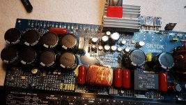
Regarding to your explaination I think this is a self-oscillating class D amp.
This is a class D type I have not worked on before.
I will probe around and hope to get more insight of how these amps work.
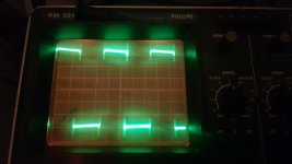
Could you please confirm this is a self-oscillating amplifier when looking to the attached images?
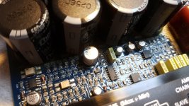
Photo 1:
Gate drive low side (50Hz sine wave input)
AC-coupled
0.2mV/div (probe 10x)
5ms/div
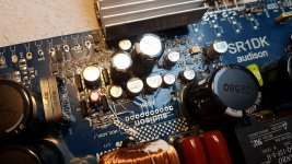
Photo 2:
Gate drive low side (50Hz sine wave input)
AC-coupled
0.2mV/div (probe 10x)
2ųs/div
There is no Gate drive on the high-side so I can't post a picture of that.
Regarding to your explaination I think this is a self-oscillating class D amp.
This is a class D type I have not worked on before.
I will probe around and hope to get more insight of how these amps work.
Could you please confirm this is a self-oscillating amplifier when looking to the attached images?
Photo 1:
Gate drive low side (50Hz sine wave input)
AC-coupled
0.2mV/div (probe 10x)
5ms/div
Photo 2:
Gate drive low side (50Hz sine wave input)
AC-coupled
0.2mV/div (probe 10x)
2ųs/div
There is no Gate drive on the high-side so I can't post a picture of that.
Attachments

Last edited:
The second image is at a higher frequency than the input signal.
If you remove the signal from the amp after it's oscillation as shown in the second image, do you still see a high frequency drive signal?
If you remove the signal from the amp after it's oscillation as shown in the second image, do you still see a high frequency drive signal?
The high frequency is not present when the audio signal is not present.
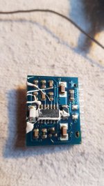
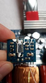
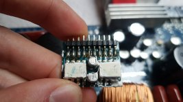
Not sure what happened here, but I wanted to check the LM219 comparator and both HCPL3180 optocouplers to see where the signal of the Hi-side stopped working correctly. So I installed some arduino wire headers to the board and driver board to be able to probe the driver board without having the risk of shorting the pins (they were very hard to probe when the driver board is installed).
Unfortunately one HCPL3180 died when applying power to the board. Not sure if there was something wrong with the headers, or the HCPL3180 was slightly killed already.
Need to order some new HCPL3180 first.
- Home
- General Interest
- Car Audio
- output IC audison SR1Dk