Hi!
I'm making an SMPS, and it's making strange things ...
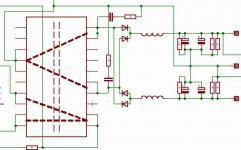
Please, look at the attached image....
When there's NOTHING (except the secondary windings 🙂 ) on the secondary side, then it's OK. When I solder in the diodes on the top and the bottom, there's also everything OK. But when I solder in one of the two "inner" diodes, then my laboratory powersupply "shows" me, that there is short-circuit somewhere.
I looked at the schematic a lot, and it seems me GOOD, so, I think, the diode-bridge is made good.
Oh, another thing: I checked the diodes with my multimeter, they were OK.
What's wrong?
I'm making an SMPS, and it's making strange things ...
Please, look at the attached image....
When there's NOTHING (except the secondary windings 🙂 ) on the secondary side, then it's OK. When I solder in the diodes on the top and the bottom, there's also everything OK. But when I solder in one of the two "inner" diodes, then my laboratory powersupply "shows" me, that there is short-circuit somewhere.
I looked at the schematic a lot, and it seems me GOOD, so, I think, the diode-bridge is made good.
Oh, another thing: I checked the diodes with my multimeter, they were OK.
What's wrong?
Attachments
Hi,
are you using a DC power supply to test your diode bridge with smoothing capacitors tacked on the end?
Then the PSU will drive current straight in to the caps and initially it looks like a short circuit.
Use AC into the bridge, start with low voltage and build up.
A variac is perfect for this but if you don't have one then use a light bulb wired in series with the live mains lead into your transformer.
The bulb starts with a lowish resistance (50r to 100r depending on wattage) and increases as it heats up. If the bridge is faulty the bulb lights and only a few mains volts appear on the input of your transformer and a tiny voltage at the bridge so nothing explodes.
If the bridge and caps are good then the bulb flashes and slowly extinguishes as the voltage on the caps builds up. This correct operation also has low start current and a small mains fuse can be used to protect everything if a serious fault exists.
This is an SMPS. On the primary side, there's a push-pull topology, with center-tapped primary-winding. Just like in the car amplifier's powersupply. I just erased the control-circuit, becouse that doesn't matter now. But if it needs, I can upload that.
Problem solved .....
I was the looser 🙂 I screwed up something with the PCB-designer software, an the PCB-drawing was wrong.

I was the looser 🙂 I screwed up something with the PCB-designer software, an the PCB-drawing was wrong.
But when I solder in one of the two "inner" diodes, then my laboratory powersupply "shows" me, that there is short-circuit somewhere.
Well, you said it, there was a short 😀
- Status
- Not open for further replies.