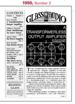
Has anyone built the Transformerless Output Amplifier described in the Volume 2, Number 2 issue of Glass Audio from 1990?
If so, might you possibly be willing to share your thoughts on it?
If so, might you possibly be willing to share your thoughts on it?
Attachments
Hi,
Yes, I did, many years ago, it is a nice sounding amp, but according to Bruce you should try it with new driver circuit from his book ( Audio Reality ) for the best possible performance.
In this case you keep the output stage and bias same as original and then you add new driver stage from his book.
Attachments
You might want to check out this fix to Bruce's circuit for equal gain, top and bottom:
The Tube CAD Journal: E-Mail, Simple tube amplifier
The Tube CAD Journal: E-Mail, Simple tube amplifier
Also read:
http://www.diyaudio.com/forums/tubes-valves/161112-what-tubes-tube-amp.html
We were making Circlotron OTLs going all the way back to the 1970s.
http://www.diyaudio.com/forums/tubes-valves/161112-what-tubes-tube-amp.html
We were making Circlotron OTLs going all the way back to the 1970s.
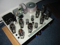
I've build it with 5 x 6AS7Gs per channel. Also modded the PSU a bit because of the iron I had. Nice amp!
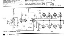
Perhaps they explain in the article, that I don't have, why the output stage is connected as it is.But it seems to me you better do it crossed.
By using the other anode the feedback has the right fase again.And now the second half of V2 is not needed anymore.
Mona
By using the other anode the feedback has the right fase again.And now the second half of V2 is not needed anymore.
Mona
Attachments
Looks like the original 2/90 version has positive local feedback in the bootstrap loop, so it does not need much voltage variation on the V3 splitter grid. So then it has more gain available in the global feedback loop.
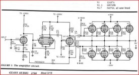
The later 3/15 modded version has negative local feedback in the bootstrap loop, so it needs a lot of voltage variation on the V3 splitter grid. And so it has less gain remaining in the global feedback loop.
Seeing as the 6AS7 is not so linear, maybe it's not so good to use it in a positive feedback loop. But then it has more gain in the global loop to fix it. Distortion contest?
Wonder if any distortion specs were given for the two variants?
Last edited:
There are some curious factors at work here, -differently-, between the two versions. Aside from the obvious full bootstrap loop effects (on V3 grid input level and global loop gain).
If you look at ONLY the 6AS7 banks (not including the required splitter grid input level effect), the local bootstrap path is N Fdbk for the 1st version, for the 6AS7s alone (but P Fdbk when including the effect on splitter input level).
(the local path looks like plate to grid Schade feedback for the 6AS7s in the 1st version, but that is crossed in the 2nd version, thru the splitter, to the opposite side grids)
Opposite for the 2nd modded version (P Fdbk for the 6AS7 bank alone, but N Fdbk when including the effect on splitter grid input level).
The V3 splitter cathode then couples the results to the other 6AS7 bank. For the 1st version, that causes the other 6AS7 bank to cooperate in the local 6AS7 (only) N Fdbk correction. The 2nd version however cooperates in the local 6AS7 (only) P-Fdbk mis-correction, making matters worse.
(ie, the very local 6AS7 loop only, N or P Fdbk, couples across the splitter cathode to give the same phase polarity correction in the other 6AS7 bank.)
So I suspect the 1st (original) version will have lower overall distortion. (-assuming- the more obvious bootstrap feedback effect on V3 input level, and the resultant global loop gain effect, come close to cancelling each other out.)
A simulation or real test results would be very informative due to the subtleties.
Last edited:
I have not build Bruce OTL amp but ,
-All that SEPP OPS 6as7g power tubes need at least 3R3 power resistors connected in cathodes circuits for better mutual current share .
- Only difference between original J.Futterman OTL circuit and Bruce circuit from post #1 is that J.Futterman accomplished full voltage gain with just one single very high gain pentode input tube and further DC connected to bootstrapped phase splitter triode ,
but Bruce OTL circuit accomplished same voltage gain in more complicated way with three triodes but AC coupled to bootstrapped phase splitter , hm I don`t see any advantage here .
The fase splitter is a cathodyne and is supposed to deliver equal voltages across the impedance on the anode and cathode impedance with both impedances equal.
The original circuit delivers the two equal voltages between anode and grid of each powertube.That makes it a Schade configuration with rather heavy NF.The splitter has to deliver the drive for the tube+ the output voltage.
Two negative sides,a cathodyne already isn't very good for high outputs and the open loop gain is low,making the overall feedback less effective.
By Xconneting the output stage the splitter only has to drive the tubes, the fase is inverted and one inverter stage less needed in the general NFB loop.
Mona
The dynamically bootstrapped ( intentionally dis-balanced ) split load ( cathodyne) phase splitter has to ideally accomplish such kind of drive for asimetric AB1 class SEPP OPS that lower power banks of power tubes ( anode followers) Ideally can never exceed unity voltage gain , but in the same time upper power banks of power tubes(cathode followers) to come close as possible(Ideally) to unity voltage gain , all that is just to get Ideal simetric output signal swing from SEPP OPS with lowest open loop THD .
I`m refer to circuit from post # 1 and original generic J.Futterman OTL circuit .
And yes I agree with Smoking Amp conclusion that lower banks of power tubes are in strong dynamic local negative feedback loop ( Shade ) .
I`m refer to circuit from post # 1 and original generic J.Futterman OTL circuit .
And yes I agree with Smoking Amp conclusion that lower banks of power tubes are in strong dynamic local negative feedback loop ( Shade ) .
Last edited:
Perhaps they explain in the article, that I don't have, why the output stage is connected as it is.But it seems to me you better do it crossed.
By using the other anode the feedback has the right fase again.And now the second half of V2 is not needed anymore.
Mona
The configuration shown in the schemo is that of an Inverted Futterman. The original Futterman didn't cross connect the finals. The originator was Julius Futterman, an amateur who didn't completely understand what was going on. It was his intention to provide the "bottom" finals -- those connected as grounded cathode amps -- with enough NFB to balance these with the "upper" cathode followers.
What Futterman forgot is that the Vpk of the cathodyne doesn't change just because you connect the bottom of the tail to the output. That caused the imposed output voltage to "shoot through" the cathodyne and appear as positive feedback for the cathode follower half of the back end. It restored balance alright, but not as Futterman intended: it made the cathode follower half into a grounded cathode stage by neutralizing the inherent cathode follower NFB. That meant all the problems of grounded cathode operation: an elevated Zo.
Cross connecting, however, does make for NFB that makes the grounded cathode half more like cathode followers.
Yes, the crossover makes for equivalent follower outputs, but then the splitter needs much more input signal on its grid, so then the global feedback is reduced.
The final result for Zo may still be the same then.
The later Rozenblit design then goes over to a differential splitter to get more drive signal headroom for equivalent'd follower outputs (after Broskie's fix to equalize the gains). But it still doesn't up the forward gain to compensate the global N Fdbk loop gain loss from the followers. With the 5687 followers now added, it could put a 6SL7 in place of the 12AU7 to increase the loop gain.
The Tube CAD Journal: E-Mail, Transcendent OTL amplifier
Last edited:
Yes, the crossover makes for equivalent follower outputs, but then the splitter needs much more input signal on its grid, so then the global feedback is reduced.
The final result for Zo may still be the same then.
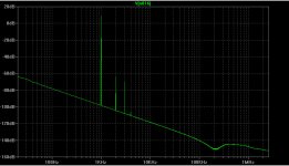
I just tried Spice simulations of the original version linked in post #1, and the cross-connected version in post #6. According to these, I am getting an output impedance of about 0.31 ohms for the original version, and about 0.27 ohms for the cross-connected version. So pretty similar.
I also looked at FFTs for a 1000Hz sinewave giving 1 W into an 8 ohm load. They are shown in the two figures (version 1, on the left, is the original, and version 2, on the right, is the cross-connected modification.)
Chris
Attachments

Last edited:
Wow, thanks greatly for the simulation. So the two versions ARE really close. One often hears about how one variant or another is so superior for Zo, and then it turns out to really make no difference for equivalent tubes. Only so much gain for local or global Fdbk to go around. I'll bet an equivalent Circlotron version splits the tiny difference.
Since follower type outputs don't really contribute much gain related "character" to the sound, I think I would just put some Mosfets in for the outputs, with lower rail voltages, and save myself all the heat for an "OTL" amp.
Since follower type outputs don't really contribute much gain related "character" to the sound, I think I would just put some Mosfets in for the outputs, with lower rail voltages, and save myself all the heat for an "OTL" amp.
Last edited:
The NFB through R22 into the V1 cathode is really the dominant factor in determining the output impedance, I guess. With that feedback, the overall gain of the amplifier is about a factor of 5, for both of the two variants. If R22 is routed to ground instead, the "open loop" gain factor is about 120 for the original, and about 115 for the cross-connected variation. The "open loop" output impedance is about 34 ohms for the original version, and about 17 ohms for the cross-connected version.
So I suppose this is showing the customary sort of considerable reduction in output impedance (34 -> 17 ohms) for driver (i.e. V3) plus output stage, when switching from original Futterman to inverted Futterman. But once the huge NFB resulting from R22 feeding back into V1 is added in, the accompanying huge reduction in output impedance largely swamps the distinction between Futterman and inverse Futterman.
Chris
Hmmm, I would have thought the original version would show maybe like 2X the open loop gain of the crossed version, with the 6AS7 Mu of 2 helping out (grounded cathode mode). But maybe the output loading of the 6AS7 is making effective Mu drop to near 1.0. Would be interesting to put a higher Mu in the 6AS7 model (or just increase the load resistance), to see what it does to the comparison specs.
One thing of interest between the two versions, is how much voltage swing occurs across the splitter tube (cathode to plate). I think that may be near equivalent also, due to the bootstrapping. But if not, it would affect what type of splitter one would want for a given version. Seeing as Bruce went to a differential splitter version later. Being able to reduce that high B+ for the front end would be a factor as well.
Don
Last edited:
- Status
- Not open for further replies.
- Home
- Amplifiers
- Tubes / Valves
- OTL Amplifier in 1990 Glass Audio Magazine