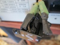
Ive been trying to fix my Hung Chang brand, (Protek 6502 model) scope that I bought second hand (in good working condition)? After it was delivered in the post I noticed that it couldn't get a .5v square wave when the probe was connected to the .5v calibration pin? and there's a spark that jumps across a 2 watt resistor in the power supply on start-up and intermittently after? I checked the scope out and found a broken (shattered) plastic voltage adjuster for 100v,120v,220v,230v,on the back next to the power plug.Ive got it set for 230v for here in Aussie land, with the fuse on the yellow 240v wire. I have the schematic for it but I cant work out why its arcing across the resistor? Could it be that the fly-back transformer has had the bomb? I have the parts list for this scope but nowhere to order them from? Where I live is fairly remote and the local repair shop cant be trusted to change the battery's in a TV remote.LOL Ive included some photos,one shows the big brown 2 watt resistor that has the arcing across it, next to the fly-back transformer. Id appreciate any help I can get.
Attachments
Maybe you should change that resistor across which the arc takes place. It does seem to have HV across it and it is old , it should degrade with time!🙂
I guess I needn't mention that you should discharge everything and wait for a while before removing it. Don't want to shock yourself inadvertently !
I guess I needn't mention that you should discharge everything and wait for a while before removing it. Don't want to shock yourself inadvertently !
Does not seem possible for a resistor to arc "along" the element unless there is a break in the resistive track. Seems like a bad component. Question is, why did the element blow open? A new one should just just fail again unless the reason for the excessive current is explored.
Does not seem possible for a resistor to arc "along" the element unless there is a break in the resistive track. Seems like a bad component. Question is, why did the element blow open? A new one should just just fail again unless the reason for the excessive current is explored.
That's basically what I'm asking, Why is it doing this? Then I might have some idea of how to fix it. The symptoms are the arcing across resistor R1017,this resistor is raised up on its pins from the PCB,I found it was pushed down so the pins were bent causing it to visibly arc? When I straightened the pins, the arc wasn't visible anymore but I can still hear it in the same general area? Actually the resistor is not 2 watts its 1 watt 22m ohms,it reads 7.20m ohms in circuit and 23m ohms out of circuit. Its associated with the focus but the focus seems OK? Ive checked all the voltages from the power supplies and there all OK although I haven't checked the 1900volt on the focus. Another thing is that I cant configure a proper .5volt square wave when I connect my probe onto the .5v config pin on the face panel? Ive tried to adjust it from the instructions in the service manual with no luck.I can get a .5v square wave on this scope if I feed it in with a signal generator? Could it be a faulty fly-back transformer (causing the arcing) or something to do with the broken voltage adjuster?
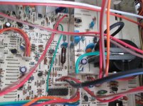
The first thing I noticed about your photo of the board is that the area around R107 doesn't look too clean, there looks to be surface contamination and fine dust on the surface- fairly typical in high voltage areas and I would bet that there are the same contaminants on the body of the resistor itself.
If you're in a high humidity climate (which I'm guessing you are) this contamination could easily be enough to cause flashovers you are seeing. As R107 is still reading correct value then it's possible that it's marginally rated for the voltage across it. Many small high value resistors can hit their maximum voltage ratings before they hit their dissipation limit. It could well be ok when clean, but it might be better to replace with a higher rated one for peace of mind - it's likely that those flashover spikes will be hitting the focus pot. I'd carefully clean the whole hv area of the PCB (after properly discharging and checking for residual voltages) with something like Isopropyl alcohol and cotton buds - not forgetting component bodies and the track side of the PCB. From the lack of other major symptoms it seems pretty unlikely that there's anything wrong with the flyback.
you seem pretty confident that you have the mains voltage selector set correctly (i thing you'd know by now if not!), so that comes down to either a replacement or safely insulated repair.
It seems that all you have left is a faulty probe cal output which seems unrelated and should hopefully be easy to fix (check the soldering of the o/p connector for a start).
Hope this helps,
Chris
I looked up your other thread 🙂
Is the trace clean (perfect focused horizontal line) when nothing is connected to the input ?
Does the trace deflect correctly for DC voltages. For example if you measure a 1.5 volt battery does the trace move the expected 1.5 squares (V/Div set to 1volt) either up or down (depending on battery polarity) ?
I looked up your other thread 🙂
Is the trace clean (perfect focused horizontal line) when nothing is connected to the input ?
Does the trace deflect correctly for DC voltages. For example if you measure a 1.5 volt battery does the trace move the expected 1.5 squares (V/Div set to 1volt) either up or down (depending on battery polarity) ?
Yes it is a clean trace with nothing on the input. With V/div set to one volt the trace moves three quarters of a square on a new AA battery that reads 1.60volt,that's with the probe on 10x? on 1x there's nothing on the screen? Ive been trying to follow the service manual instructions but my signal generator only goes to 5 volts amplitude. I hope this is making sense?
You may have a carbon track across that resistor that is arcing. It may have been coated in dust in the past, then became damp and arced. When it arcs it leaves a carbon trail that is prone to arc again. This is common in 600VAC 3 phase and automotive ignition coils. Try just replacing it and see if it's good.
Gyro, I'm down wind from an iron ore and copper concentrate loading operation at the Geraldton wharf and it looks like the dust is getting in the scope I gave it a quick clean and it only gave one little arc,as apposed to 2 or 3 big ones,plus there is high humidity here at the moment.Ill give it a wash today to get it all out.
Yes it is a clean trace with nothing on the input. With V/div set to one volt the trace moves three quarters of a square on a new AA battery that reads 1.60volt,that's with the probe on 10x? on 1x there's nothing on the screen? Ive been trying to follow the service manual instructions but my signal generator only goes to 5 volts amplitude. I hope this is making sense?
Not sure what to make of that. The probe is an unknown, just connect the battery direct to the input socket and ground with a bit of wire. The trace should move the expected amount on 1V/Div. If it doesn't then there is a problem with the Y amplifier but that "problem" could be anywhere along the signal path. Try 10V/Div. Does the trace move a tenth of a square upwards ?
Not sure what to make of that. The probe is an unknown, just connect the battery direct to the input socket and ground with a bit of wire. The trace should move the expected amount on 1V/Div. If it doesn't then there is a problem with the Y amplifier but that "problem" could be anywhere along the signal path. Try 10V/Div. Does the trace move a tenth of a square upwards ?
I changed the probe for another one and with the V/div at 1v and the probe set at 1x it moves 1 square when measuring a new 1.6v battery and 2 squares set on .5v.
That points to either a problem with the Y amplifier or it could simply need calibrating. If you look at the highest sensitivity setting for the Y amp (say 5mv/Div) then that sets the basic gain for the whole chain. You need to rig a simple voltage divider up across the battery (resistor and preset pot) that will allow you to set approx 5mv as a reference (if that is what the highest setting is) and take things from there. You would then adjust the Y gain to give 1 square deflection for your applied 5 millivolts.
(The adjustment should be done on the highest sensitivity which takes the input attenuator of the scope out of the equation)
(The adjustment should be done on the highest sensitivity which takes the input attenuator of the scope out of the equation)
I'll just add that you should confirm if possible that the basics such as supplies are all correct. If the EHT to the CRT is high then electron beam becomes harder to deflect and that would show as a reduced sensitivity.
Without a special EHT probe you probably have no real way of measuring that but a worthwhile check might be to confirm that the X axis is basically correct (does your 1kHz cal signal seem to be displayed correctly on the X axis ?). For example 1Khz as a period of 1ms and so if yo set the timebase to 10ms you should see 10 cycles displayed. If that were out as well then you start to need looking a bit deeper at what may have happened to this scope.
Without a special EHT probe you probably have no real way of measuring that but a worthwhile check might be to confirm that the X axis is basically correct (does your 1kHz cal signal seem to be displayed correctly on the X axis ?). For example 1Khz as a period of 1ms and so if yo set the timebase to 10ms you should see 10 cycles displayed. If that were out as well then you start to need looking a bit deeper at what may have happened to this scope.
With this new probe I'm getting a distorted .5v calibration square wave but it doesn't adjust to normal with any of the VRs that the service manual says to adjust? I'm drying the scope out at the moment after washing all the conductive crap out of it. Ill do that 1khz 1ms test tomorrow when its dry and get back to you with the results.Thanks Mooly,I feel like I'm getting somewhere now!
Last edited:
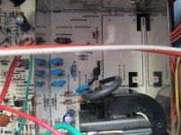
I washed and dried the bottom board and it was OK after turn on for about 10 minutes,I remeasured all the DC voltages on the power supply to make sure they were OK and thought I had it fixed, then it started intermittently sparking again but this time it was at the cathode end of D1012? The D1012 diode was recently replaced with an equivalent because when I measured it I couldn't get a forward voltage measurement,so when I got the replacements I measured one before installing it and it was the same! It didn't have a forward voltage either? so I put it in anyway assuming that that's just the way these high voltage ones are? I noticed that the main transformer is getting really hot? Hot as in I couldn't hold my finger on it for longer than a couple of seconds?
Its hard to say tbh. The transformer probably will be hot after its been powered up for some time... particularly when used in a hot climate too. True EHT diodes will read strange on a DVM, an older analogue meter (AVO8) would get them to conduct in the forward direction. Long time since I've measured any tbh and the ones I dealt with were around 35 to 50 mm long from memory.
What is the diode sparking to ? is it another component or just arcing across itself.
What is the diode sparking to ? is it another component or just arcing across itself.
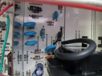
The diode isn't arcing across to anything now? Before I cleaned it up it was arcing across to the base of the black wire on the right in the photo as well as the 22m ohm resistor arcing across itself and to a wire link next to it but now its just a tiny (but loud) spark on the left side on the 2kv diodes cathode pin? The spark is actually on the pin itself,weird! Ive checked the diode with an analog MM and it reads OK.This is a strange one,Ive checked transistors, electrolytic caps,solder-bridges etc...Oh well,it looks like Ive bought a lemon.
Attachments
- Status
- Not open for further replies.
- Home
- Design & Build
- Equipment & Tools
- Oscilloscope repair?