Tek recently published this: Probe Performance and Measurement | Tektronix which is a redo of one of their classic intros. Its quite good judging from what I have read so far and a must read for anyone using an oscilloscope with a probe.
A series of seven blog entries about probes
Test Happens - Teledyne LeCroy Blog: Putting Probes in Perspective
Test Happens - Teledyne LeCroy Blog: Secrets of the 10x Passive Probe
Test Happens - Teledyne LeCroy Blog: How Equalization Works in 10x Passive Probes
Test Happens - Teledyne LeCroy Blog: How Tip Inductance Impacts a Probing System's Bandwidth
Test Happens - Teledyne LeCroy Blog: 10x Passive Probes and Cable Reflections
https://blog.teledynelecroy.com/2018/12/squeezing-more-bandwidth-from-10x.html
https://blog.teledynelecroy.com/2018/12/using-50-ohm-coax-from-dut-to.html#more
George
>Edit. One more
https://blog.teledynelecroy.com/2020/08/how-do-you-choose-whether-to-use-50-ohm.html#more
Main things are to calibrate the probe to a square wave.
Use x10/x100 probes where possible as they lose high frequencies less than x1.
Use x10/x100 probes where possible as they lose high frequencies less than x1.
Right Nigel. Probe compensation is important.
Demian’s linked paper and Teledyne’s blog hint to other aspects that are important too.
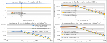
Here is some low frequency impedance measurements taken at the tip of probes (DER DE-5000). showing the loading effect a probe imposes on the probed circuit.
For impedance data at higher frequencies, a nanoVNA will be handy (when it will arrive)
George
Demian’s linked paper and Teledyne’s blog hint to other aspects that are important too.
Here is some low frequency impedance measurements taken at the tip of probes (DER DE-5000). showing the loading effect a probe imposes on the probed circuit.
For impedance data at higher frequencies, a nanoVNA will be handy (when it will arrive)
George
Attachments
The problem with a scope is it not only has input impedance but also input capacitance.
So in x1 mode your higher frequencies will be low pass filtered due to 10pf input capacitance.
In x10 mode the probe has a resistance and cap in parallel in series with probe and this cap cancels out 10pf input capacitance hence better higher frequency response.
So in x1 mode your higher frequencies will be low pass filtered due to 10pf input capacitance.
In x10 mode the probe has a resistance and cap in parallel in series with probe and this cap cancels out 10pf input capacitance hence better higher frequency response.
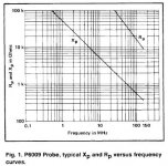
Some vendors provide the effective input impedance info. Attached for the Tek P6009 X100 probe I recently bought.
The P6009 is only rated to 100 MHz but actually measures to 200 MHz in the scope (2nS rise time). Its also good for 1500V so I can recommend it for working on tube stuff.
Other vendors have similar info but in my experience a good vintage Tek or HP probe will usually have better waveform fidelity than a cheap new probe.
Its interesting that a X100 probe input impedance can drop so much at high frequencies. Probably not an issue for audio.
Attachments
1st post
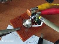
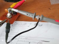
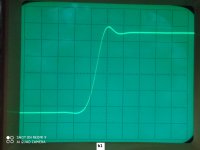
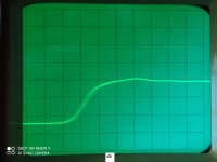
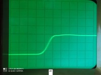
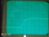
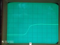
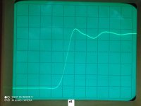
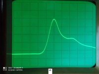
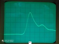
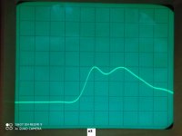
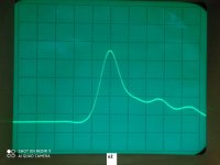
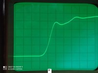
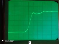
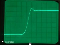
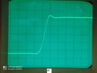
I took some shots of an 100MHz BW oscilloscope screen to show the effect of probe and input impedance.
A diy step generator producing a 2.2-2.5ns rise time (10%-90%) step.
Generator Rout:48 Ohm
Oscilloscope Rin 1 MOhm//20pF or 50 Ohm selectable.
attachments:
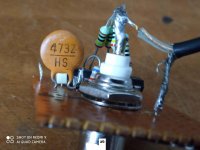
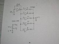
a1 schematic
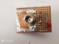
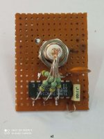
a2 top side
a3 bottom side
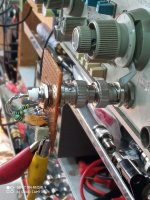
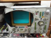
a4 HP1741A
a5 direct connection
a6 cable connection
a7 probe with long gnd lead
a8 probe with short gnd lead
a9 pulse on HP1741A
a10 pulse on TEK 475
George
>edit.Last screenhot kindly provided by member https://www.diyaudio.com/forums/members/mkerk.html
I took some shots of an 100MHz BW oscilloscope screen to show the effect of probe and input impedance.
A diy step generator producing a 2.2-2.5ns rise time (10%-90%) step.
Generator Rout:48 Ohm
Oscilloscope Rin 1 MOhm//20pF or 50 Ohm selectable.
attachments:
a1 schematic
a2 top side
a3 bottom side
a4 HP1741A
a5 direct connection
a6 cable connection
a7 probe with long gnd lead
a8 probe with short gnd lead
a9 pulse on HP1741A
a10 pulse on TEK 475
George
>edit.Last screenhot kindly provided by member https://www.diyaudio.com/forums/members/mkerk.html
Attachments
-
 a10.jpg557.6 KB · Views: 83
 -
 a9.jpg452.4 KB · Views: 80
 -
 a8 short gnd lead.jpg501.7 KB · Views: 75
 -
 a7 long gnd lead.jpg483.4 KB · Views: 75
 -
 a6 RG59 soldered.jpg542.1 KB · Views: 86
 -
 a5 direct connection.jpg468.8 KB · Views: 89
 -
 a4 oscilloscope.jpg702.6 KB · Views: 85
 -
 a3 bottom side.jpg490.9 KB · Views: 182
 -
 a2 top side.jpg258.6 KB · Views: 184
 -
 a1 schematic.JPG539 KB · Views: 197

2nd post
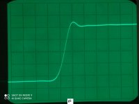
(x1)probes to 1 MOhm//20pF input.
1V/div - 5ns/div
Step generator connected through:
b1 male to male BNC adaptor
b2 e-bay 100MHz (x1)probe with a ground lead length of 23mm
b3 same e-bay 100MHz (x1)probe, now with a ground lead length of 160mm
b4 e-bay P6100 (x1)probe with a ground lead length of 23mm
b5 same e-bay P6100 (x1)probe, now with a ground lead length of 160mm
George
Attachments
3rd post
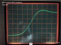
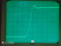
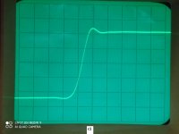
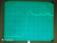
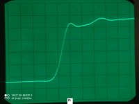
(x1)probes to 50 Ohm input
.5V/div - 5ns/div
Step generator connected through:
c1 male to male BNC adaptor
c2 e-bay 100MHz (x1)probe (x1) with a ground lead length of 23mm
c3 same e-bay 100MHz (x1)probe, now with a ground lead length of 160mm
c4 e-bay P6100 (x1)probe with a ground lead length of 23mm
c5 same e-bay P6100 (x1)probe, now with a ground lead length of 160mm
George
Attachments
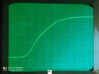
4th post
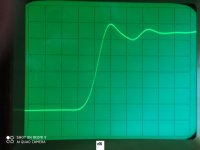
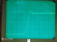
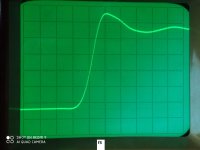
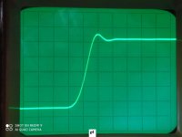
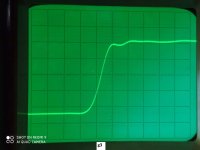
(x10)probes to 1 MOhm//20pF input.
.1V/div - 5ns/div
Step generator connected through:
d1 TEK P6108A 100MHz (x10)probe with a ground lead length of 23mm
d2 TEK P6108A 100MHz (x10)probe (x10) with a ground lead length of 180mm
d3 e-bay 100MHz (x10)probe with a ground lead length of 23mm
d4 same e-bay 100MHz (x10)probe, now with a ground lead length of 160mm
d5 e-bay P6100 (x10)probe with a ground lead length of 23mm
d6 same e-bay P6100 (x10)probe, now with a ground lead length of 160mm
George
Attachments

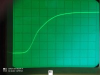
5th post
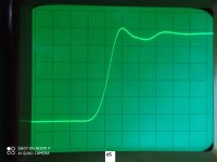
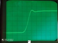
(x10)probes to 50 Ohm input
.05V/div - 5ns/div
Step generator connected through:
e1 TEK P6108A 100MHz (x10)probe with a ground lead length of 23mm
e2 TEK P6108A 100MHz (x10)probe (x10) with a ground lead length of 180mm
e3 e-bay 100MHz (x10)probe with a ground lead length of 23mm
e4 same e-bay 100MHz (x10)probe, now with a ground lead length of 160mm
e5 e-bay P6100 (x10)probe with a ground lead length of 23mm
e6 same e-bay P6100 (x10)probe, now with a ground lead length of 160mm
George
Attachments

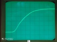
6th post
cables to 1 MOhm//20pF input.
1V/div - 5ns/div
Step generator connected through:
f1 male to male BNC adaptor
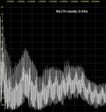
f2 0.43m long RG174 coaxial cable, directly soldered to the gen out
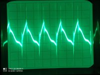
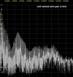
f3 0.43m long twisted CAT5 pair, directly soldered to the gen out
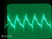
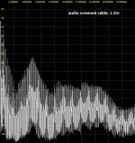
f4 0.43m long audio coaxial cable, directly soldered to the gen out
f5 1.3m long RG174 coaxial cable, directly soldered to the gen out
f6 1.3m long twisted CAT5 pair, directly soldered to the gen out
f7 1.3m long audio coaxial cable, directly soldered to the gen out
George
cables to 1 MOhm//20pF input.
1V/div - 5ns/div
Step generator connected through:
f1 male to male BNC adaptor
f2 0.43m long RG174 coaxial cable, directly soldered to the gen out
f3 0.43m long twisted CAT5 pair, directly soldered to the gen out
f4 0.43m long audio coaxial cable, directly soldered to the gen out
f5 1.3m long RG174 coaxial cable, directly soldered to the gen out
f6 1.3m long twisted CAT5 pair, directly soldered to the gen out
f7 1.3m long audio coaxial cable, directly soldered to the gen out
George
Attachments


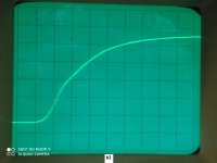
7th post (last one)
cables to 50 Ohm input.
1V/div - 5ns/div
Step generator connected through:
g1 male to male BNC adaptor
g2 0.43m long RG174 coaxial cable, directly soldered to the gen out
g3 0.43m long twisted CAT5 pair, directly soldered to the gen out
g4 0.43m long audio coaxial cable, directly soldered to the gen out
g5 1.3m long RG174 coaxial cable, directly soldered to the gen out
g6 1.3m long twisted CAT5 pair, directly soldered to the gen out
g7 1.3m long audio coaxial cable, directly soldered to the gen out
George
Attachments
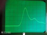
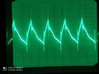
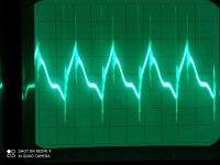
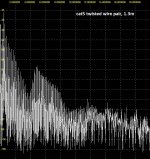
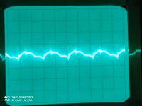
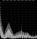
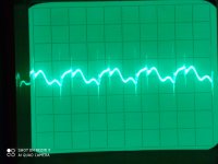
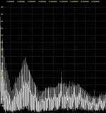
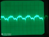
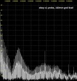
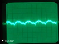
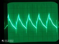
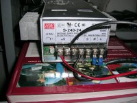
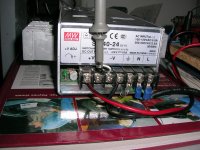
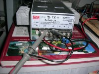
Here is the probing on a Meanwell S240-24 SMPS output on 3 Ohm load (8A)
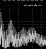
Attachments are in pairs Oscilloscope screen and it’s FFT
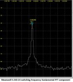
Oscilloscope input set to 50 Ohm. All oscilloscope screenshots are .01V/div _ 5μsec/div
FFt is through a 50 Ohm input SDR (SDRplay RSP1A). All are harmonics of 92.4kHz switching freq.
George
Attachments are in pairs Oscilloscope screen and it’s FFT
Oscilloscope input set to 50 Ohm. All oscilloscope screenshots are .01V/div _ 5μsec/div
FFt is through a 50 Ohm input SDR (SDRplay RSP1A). All are harmonics of 92.4kHz switching freq.
George
Attachments
-
 5 RG174-130cm.jpg160.7 KB · Views: 58
 -
 5.jpg435.9 KB · Views: 55
 -
 4 audio-43cm.jpg162.3 KB · Views: 59
 -
 4.jpg429.8 KB · Views: 60
 -
 3 audio-130cm.jpg161.7 KB · Views: 51
 -
 3.jpg458.5 KB · Views: 66
 -
 2 cat5-43cm.jpg161.6 KB · Views: 52
 -
 2.jpg426.9 KB · Views: 60
 -
 1 cat5-130cm.jpg160.8 KB · Views: 60
 -
 1.jpg460.3 KB · Views: 61
continuous
Attachments
-
 9.jpg358.4 KB · Views: 58
 -
 9 ebay P6100 x1 probe-23mm gnd lead.jpg145.9 KB · Views: 55
 -
 10.jpg356.5 KB · Views: 53
 -
 10 ebay P6100 x1probe-23mm gnd lead.jpg150.5 KB · Views: 50
 -
 8 ebay P6100 x1 probe-160mm gnd lead.jpg150 KB · Views: 60
 -
 8.jpg339.5 KB · Views: 54
 -
 7 ebay x1 probe-160mm gnd lead.jpg152 KB · Views: 56
 -
 7.jpg353.5 KB · Views: 62
 -
 6 RG174-43cm.jpg161 KB · Views: 68
 -
 6.jpg444.3 KB · Views: 60

Yep, test points with BNC or SMA connectors are quite useful.
https://www.newark.com/cal-test-electronics/ct3655/bnc-adapter-3-5mm-oscilloscope/dp/80AC8637
https://www.newark.com/cal-test-electronics/ct3655/bnc-adapter-3-5mm-oscilloscope/dp/80AC8637
- Home
- Design & Build
- Equipment & Tools
- Oscilloscope probe primer