Hi folks...
I was given a pair of Musical Fidelity X-A200 monoblocks to look at for a friend.
One was supposedly working, the other had a massive turn-on thump and gross distortion.
I repaired the problem one - it needed caps, a couple of resistors and some transistors. It now works perfectly.
However, when testing I noticed the other, supposedly working one had a really high level of hiss. Music plays and doesn't sound distorted but the hiss is always present even with the input shorted.
The amp biases up correctly and bias is stable. It doesn't seem to get any hotter than the working one
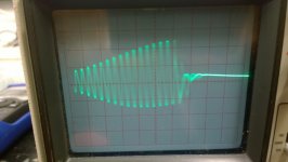
Broke out the 'scope and below is what I see on the speaker terminals. It's the same with or without a load connected.
Pictures are at 2v/div. So there appears to be an 8v p-p burst oscillation.
Picture 1 is at 10us/div so the bursts are at about 35kHz.
Picture 2 is at 0.5us/div zoomed into one of the bursts showing about a 5MHz oscillation.
The other amp (the one I repaired doesn't show anything).
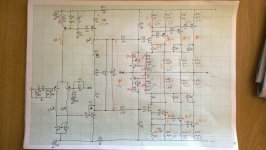
Picture 3 is a rough (very rough) tracing of the circuit from when I had the other amp apart.
All small sig transistors are mpsa42 & 92 and input pair up to VAS seems pretty standard.
The cfp output stage is a buz901 & 906 driving parallel mag1832 & 2013 (2sc5200 & 2sa1493 in my repaired and working amp). This is the part I'm not too familiar with...
Anyone seen this type of oscillation before who might be able to point me in the direction of a cure?
John
I was given a pair of Musical Fidelity X-A200 monoblocks to look at for a friend.
One was supposedly working, the other had a massive turn-on thump and gross distortion.
I repaired the problem one - it needed caps, a couple of resistors and some transistors. It now works perfectly.
However, when testing I noticed the other, supposedly working one had a really high level of hiss. Music plays and doesn't sound distorted but the hiss is always present even with the input shorted.
The amp biases up correctly and bias is stable. It doesn't seem to get any hotter than the working one
Broke out the 'scope and below is what I see on the speaker terminals. It's the same with or without a load connected.
Pictures are at 2v/div. So there appears to be an 8v p-p burst oscillation.
Picture 1 is at 10us/div so the bursts are at about 35kHz.
Picture 2 is at 0.5us/div zoomed into one of the bursts showing about a 5MHz oscillation.
The other amp (the one I repaired doesn't show anything).
Picture 3 is a rough (very rough) tracing of the circuit from when I had the other amp apart.
All small sig transistors are mpsa42 & 92 and input pair up to VAS seems pretty standard.
The cfp output stage is a buz901 & 906 driving parallel mag1832 & 2013 (2sc5200 & 2sa1493 in my repaired and working amp). This is the part I'm not too familiar with...
Anyone seen this type of oscillation before who might be able to point me in the direction of a cure?
John
Attachments

Strange problem. Does this amp look like it has ever been worked on in the past ? Can you be sure the semiconductor are original ?
Its always worth doing a scope check of the rails and also across C7 and C9.
Its always worth doing a scope check of the rails and also across C7 and C9.
Semis look original and are the same as those that were in the other amp.
The main rails show 100hz ripple about 0.4v p-p. The negative triangular'ish, the positive more sawtooth.
C7 and C9 both have about 40mV p-p 100hz ripple.
Otherwise clean...
The main rails show 100hz ripple about 0.4v p-p. The negative triangular'ish, the positive more sawtooth.
C7 and C9 both have about 40mV p-p 100hz ripple.
Otherwise clean...
Is their a Zobel network / Boucherot cell across between the output and ground not shown on the circuit diagram?
If so is the resistor and capacitor intact? They can help to keep the output stage stable.
If so is the resistor and capacitor intact? They can help to keep the output stage stable.
Is their a Zobel network / Boucherot cell across between the output and ground not shown on the circuit diagram?
If so is the resistor and capacitor intact? They can help to keep the output stage stable.
Yes, not shown on diagram. 3 x parallel 15R resistors and 220nF cap to ground, 3R3 resistor and coil to binding posts.
Seem to test ok.
I haven't seen this type of instability from dodgy zobel though.... has anyone?
All very strange.
I think as first step that you need to try and get a handle on where the problem lies.
I would be tempted to look at all the small value caps that keep stability under control, not so much that they could be faulty but just to see where it leads. So I would probably look at paralleling them all, and just one at a time, with something around 30 to 50% of the value fitted and see what effect that has.
The zobel network... and everything else really... don't overlook anything like damaged print that is causing a floating ground.
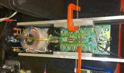
I'll give that a try. So C5, 6, 10&11 and the zobel right? This could take a while since the amps need to be removed from the tubular chassis and then the psu, speaker and input woring unsoldered and the pcb's taken off an aluminium sub plate before I can get to the bottom solder side... These things weren't made for ease of servicing!
Here's the other one I had out and mounted to a temporary heatsink while testing...
Here's the other one I had out and mounted to a temporary heatsink while testing...
Attachments
The instability frequency tends to make me think it is the output stage oscillating.
The resistors and capacitors in series with the MOSFET gates along with the 5R Zobel network look like trial and error design to keep the output stage from oscillating. The transistor type change could require another round of experimentation to keep the stage from oscillating.
The resistors and capacitors in series with the MOSFET gates along with the 5R Zobel network look like trial and error design to keep the output stage from oscillating. The transistor type change could require another round of experimentation to keep the stage from oscillating.
Except the other amp, that I had to replace transistors in, is working perfectly! This one is original...
C2, 5, 6, 8, 10 and 11. And the Zobel. You can just dab a 4.7 to 10 ohm and series 0.1uf to ground to check that. Be sure to take the Zobel direct from the output line we can see on your diagram and before any output inductor (if fitted)
You might be able to get some initial clues by first just putting a finger on and around the small caps and seeing if it alters anything. Unstable amps typically vary enormously as a bit of stray capacitance is introduced around any problem area.
You might be able to get some initial clues by first just putting a finger on and around the small caps and seeing if it alters anything. Unstable amps typically vary enormously as a bit of stray capacitance is introduced around any problem area.
I'm sorry I should have read the original post properly.Except the other amp, that I had to replace transistors in, is working perfectly! This one is original...
Interestingly, I removed the amp from its case and clamped it to some temporary flat bar heatsinks as per my earlier pic....
Now the oscillation is a constant 2V p-p 5MHz without the 35kHz "burst"...
Since the actual case is grounded I grounded my temporary heatsinks together to the mains earth tag and the "Burst" comes back as per my first post...
Now to increase the caps one by one...
Oh, I also notice there's a 470pf right across the speaker outputs too... another attempt at stabilising?
I tacked a 180pf across each of the two 330pf caps on the mosfet gates...
Now I notice the following changes...
Oscillation looks much like in post one but a bit blurrier(?) on the scope.
I also noticed the bias value (across output emitter resistor) had decreased from 20mV to 8mv... Tried to adjust bias and it rises to 10mV at about 60% on the pot and then drops to 0. When it drops to 0 the oscillation also disappears. When I turn the pot back down the bias suddenly re-appears at about 10mV and can be adjusted down from there. When the bias comes back the oscillation comes back.
I removed the ground connection from the heatsinks and see the following:
5MHz oscillation of varying amplitude but about half what it was previously.
Bias is back to being fully adjustable throughout range of pot.
Shape of envelope of oscillation amplitude varies with adjustment of pot!
Very odd!
Removed the temporary 180pf caps and tacked in a 10R+100nF across existing zobel RC...
Heatsink grounded - Flatline! No sign of oscillation! Bias adjustable throughout range!
This looks promising!
I'll do some more testing and connect up a speaker before celebrating too much!
Heatsink grounded - Flatline! No sign of oscillation! Bias adjustable throughout range!
This looks promising!
I'll do some more testing and connect up a speaker before celebrating too much!
The 470pf could be to try and stop rf (radio frequency) interference getting into the amp via the speaker leads acting as long wire aerials.
If there a problem around the 330pf caps then bridging them would kill the oscillation instantly.
The fact its changed when you remove the amp from its case is pointing to something critical in the grounding of it all. No screws missing when its all assembled ?
Faults like this are hard to diagnose without having it in front of you. Using your scope, select the main grounding point in the amp for the scope probe ground and then check the ground points in the amp with the scope. Make sure that they are at ground and that no hash/oscillation is seen. Make sure the input ground is clean and also the feedback ground return on C4.
Removed the temporary 180pf caps and tacked in a 10R+100nF across existing zobel RC...
Heatsink grounded - Flatline! No sign of oscillation! Bias adjustable throughout range!
This looks promising!
I'll do some more testing and connect up a speaker before celebrating too much!
Oooh. Now that does sound interesting. Could the original cap in the Zobel be open circuit ?
That's the weird thing. The cap reads 220nF on the Peak LCR meter. The 15R resistors read 15R! There's continuity from the ground side of the cap to ground, from the cap to the resistors and from the output side of the resistors to the output stage!
I replaced the 220nF with a 470nF and left the resistors alone - stable!
It's back in its box and playing music and all is well with the world...
I can only think that these things are right on the edge of instability and something's drifted just enough to push it over the edge!
Part of it must stem from capacitance across the silpad insulating the outputs to ground...
Makes me really dislike amp designers who design things so close to broken!
Thanks Mooly and Pchi for the input!
That all sounds very promising. Normally the Zobel network is pretty uncritical, 47nf, 470nf 4.7 ohm, 15 ohm, it doesn't normally make any real difference as long as 'something' is there.
It would be interesting to try a new 220nf for curiosity but the 470nf will be fine.
Things like that are weird, and as you say, it may well be a design on the edge of instability.
It would be interesting to try a new 220nf for curiosity but the 470nf will be fine.
Things like that are weird, and as you say, it may well be a design on the edge of instability.
Greetings, All.
I didn't want to open a new post for this, since some things that I was interested in are covered in this thread.
I've swapped out all the e-caps in my X-A200s (seemed like a good idea given their age) and have adjusted the current bias, on the basis of the emitter resistor voltage drop for each of the first pair of output devices in each amp. The drop across the emitter resistors in one amp was almost nothing, and for the other amp it was quite low at around 8mV. No wonder they barely got warm 😀.
I upped those so that values in terms of mV are sitting roughly in the mid twenties.
I've never found a service manual for these amps, so was hoping someone could indicate what the actual specified ideal bias level is?
Am I likely OK with what I've done? Hottest part of case doesn't go over 40C at normal listening levels. In the first post on this thread, the schematic shows slightly different voltages across all emitter resistors, sort of what I'm getting. Will have to check the other emitter resistors as well I guess.
On another matter, the DC Offset in one amp is ... zero (ok, maybe 1 mV sometimes), but in the other it is around 38 mV (both before and after recapping and bias adjustments). I gather this is not really high enough to worry about and that in any case, there's nothing relatively simple I can do to drop the DC Offset?
I've had the amps for 22 years.
Many thanks.
Cheers,
Nicholas
To answer my own question regarding DC-Offset: changing the input pair of transistors. At 38 mV I'll leave it alone for now. If it eventually drifts above, say 50 mV, I might look at this option.
- Home
- Amplifiers
- Solid State
- Oscillating Muscial Fidelity X-A200