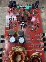
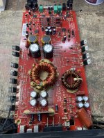
This happened often in a different type of amplifier when the drive for half of the output FETs was defective.
What type of scope do you have?
What type of scope do you have?
Found it,a rusty leg on a transistor in the drive circuit and the optocoupler.
I have both Analog and digital scope
I have both Analog and digital scope
Is the digital, handheld or is it mains powered?
If not handheld, do you know how to use your mains powered scopes in differential mode?
If not handheld, do you know how to use your mains powered scopes in differential mode?
After replacing the parts rail is equal now. I gave it a run and all seem ok.
Scope is mains powered,am planning to buy a handheld one but to many options not sure which one to buy yet.
Scope is mains powered,am planning to buy a handheld one but to many options not sure which one to buy yet.
Using differential mode will give you the same ability to read the signal alone (no DC, no rail-rail swing) and if using the analog scope, will give you a great quality waveform display.
A differential input uses two inputs to produce a single waveform. The simplest way to get a differential input is to use a differential probe. A differential probe has two signal leads and a mixer amplifier built into it. It feeds the scope a normal signal (a composite of the two signals input into the differential probe). The problem with differential probes is that they're expensive.
The alternative is to use two scope probes and and both inputs of your oscilloscope. This is how you have to set up your scope:
Two probes
Both scope inputs used
Input set to add
Both channels set to DC coupling
Both channels set to 'cal'.
Both vertical amps set to the same voltage
Ch2 input set to invert
Bandwidth limited (works best for most measurements in car amps)
Trace aligned to the reference line on the scope's display
Ground leads for both probes connected together (not always necessary)
After setting up the scope, you need to confirm that it's working as it should. With the vertical amp set to 5v/div, touching the probe that's connected to Ch1 to the positive terminal of your 12v power supply should make the trace deflect about 2.5 divisions up from the reference (like it always does, seen below). Doing the same with the probe connected to Ch2 should make the trace deflect down about 2.5 divisions. Touching both probes to the positive terminal of the 12v power supply should cause no deflection. If it does, something isn't right.
I know that this may not be as simple as the isolated scope but if you take the time to learn it one time (even if it takes an hour or more of your time), you have that knowledge and this tool to use for the rest of the time you need to use a scope. Using the analog scope will give you much larger and cleaner waveforms.