Push-pull EF or 2EF output stage is probably the most frequently used output topology in class AB amplifiers. It is well covered in renowned design handbooks, like
Self, D.: Audio Amplifier Design Handbook (Newness)
or
Cordell, B.: Designing Audio Power Amplifiers (McGraw Hill)
Authors come to the conclusion that for the lowest distortion in class AB, voltage drop across an Re resistor (usually 0.1 to 0.47 ohm) should be about 22mV, as by Self below (he shows voltage between emitters, i.e. 2 x Re resistor):

Simulators (MicroCap, LTSpice) show +/- similar values. But how about real amplifiers? Is it a general rule? My experience says that sometimes yes, sometimes no, depending on the amplifier circuit.
I am posting an example of the amplifier where this general rule does not work. It is the remake of 1969 Sinclair Z-30 amplifier:

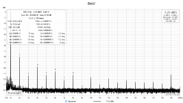
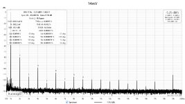
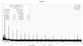
Re resistor (R14, R15) is 0R22. Optimal bias should be (according to Self) 23.1mV per Re. I have measured spectra at moderate power (4R7 load) for 8mV, 14mV and 21mV per Re, i.e. idle current 36mA, 64mA and 95mA. Below are the results.


The distortion is almost same in all 3 cases, slight differences are in high order distortion components. Something does not fit. Let's measure distortion as a function of output voltage and idle current:

And now we have it. It is something that we would intuitively expect. At low power, the higher the idle current, the lower distortion, because the output stage stays longer in the class A. The lowest distortion is for 50mV across Re, resulting in 227mA idle current. Now we are up to 0.48W in class A for 4R7 load (green trace). About 2.5x Self's optimal bias point. So? Isn't it better to design for lowest measured distortion, rather than follow textbook suggestions? And, BTW, this amplifier has flat THD vs. frequency up to 10kHz, measured with 90kHz BW.

Self, D.: Audio Amplifier Design Handbook (Newness)
or
Cordell, B.: Designing Audio Power Amplifiers (McGraw Hill)
Authors come to the conclusion that for the lowest distortion in class AB, voltage drop across an Re resistor (usually 0.1 to 0.47 ohm) should be about 22mV, as by Self below (he shows voltage between emitters, i.e. 2 x Re resistor):
Simulators (MicroCap, LTSpice) show +/- similar values. But how about real amplifiers? Is it a general rule? My experience says that sometimes yes, sometimes no, depending on the amplifier circuit.
I am posting an example of the amplifier where this general rule does not work. It is the remake of 1969 Sinclair Z-30 amplifier:
Re resistor (R14, R15) is 0R22. Optimal bias should be (according to Self) 23.1mV per Re. I have measured spectra at moderate power (4R7 load) for 8mV, 14mV and 21mV per Re, i.e. idle current 36mA, 64mA and 95mA. Below are the results.


The distortion is almost same in all 3 cases, slight differences are in high order distortion components. Something does not fit. Let's measure distortion as a function of output voltage and idle current:
And now we have it. It is something that we would intuitively expect. At low power, the higher the idle current, the lower distortion, because the output stage stays longer in the class A. The lowest distortion is for 50mV across Re, resulting in 227mA idle current. Now we are up to 0.48W in class A for 4R7 load (green trace). About 2.5x Self's optimal bias point. So? Isn't it better to design for lowest measured distortion, rather than follow textbook suggestions? And, BTW, this amplifier has flat THD vs. frequency up to 10kHz, measured with 90kHz BW.

What frequency did you bench at? How about 10KHz.
I did some math behind it sometime ago. The result confirmed what Douglas Self suggested. One assumption is that the output transistors are driven by voltage source. Any impedance shown up at the base of transistor could be transferred to the emitter. That may mess up the setup.
As your VAS is just a single transistor and the Miller cap is relatively small, the output impedance of the VAS is high.
I also did extensively simulation with the Blameless EF2 topology. The simulation also agrees the optimal bias point is about 100mA for 0.22 Ohm Re. I will share this later.
It is the derivative of transfer function (v(out)/v(in)) that has the decisive role. It must be as smooth as possible, without peaks and dips. (R29 is bias trimpot resistance, v6 is input voltage)

It is even much much worse with MOSFETs.I guess these results only apply to BJTs?
Not to Mosfet outputs?
"Optimum bias" 21mV/0R22 (by Self) vs. "overbiased" (50mV/0R22) at 3.5V/4R7 - please note that higher bias has both lower THD and faster decay of high order distortion components. Of course going down to 1V with output voltage the differences become bigger.
"Optimum" bias

"Overbiased"

19kHz is air induced FM pilot frequency due to non-shielded sample setup.
"Optimum" bias
"Overbiased"
19kHz is air induced FM pilot frequency due to non-shielded sample setup.
Very interesting.
Two observations:
Self's data is for an 8 Ohm load. You are testing with 4R7. How does that make a difference?
Also, you are testing for Iq's up to Self's recommendations. What about going higher?
Two observations:
Self's data is for an 8 Ohm load. You are testing with 4R7. How does that make a difference?
Also, you are testing for Iq's up to Self's recommendations. What about going higher?
From the other thread:
You need to compare the measurements against simulation. I expect that the device parameters can be adjusted to get a good match.
The 22mV rule applies only to a complementary emitter follower class AB output stage driven by a voltage source. This is the dominant source of distortion in my amplifier (and I suspect all good amplifiers). The amplifier you are measuring did not try to minimize other sources of distortion.
Ed
EdGr said:I think the distortion you are measuring is due to Hfe differences between NPNs and PNPs, variations in Hfe with Ic, and/or non-linearities in the VAS. These can far exceed the distortion due to the exponential current-voltage relationship.
Analyzing the causes of distortion is an intractable problem unless one makes simplifying assumptions (and designs the amplifier so that those assumptions hold true). I have now written special-purpose simulators for all of the blocks in my amplifier, and I think I have a good understanding of the distortion mechanisms. I can explain why simulators don't always produce the right answers.
Ed
You need to compare the measurements against simulation. I expect that the device parameters can be adjusted to get a good match.
The 22mV rule applies only to a complementary emitter follower class AB output stage driven by a voltage source. This is the dominant source of distortion in my amplifier (and I suspect all good amplifiers). The amplifier you are measuring did not try to minimize other sources of distortion.
Ed
This is IMO the best way how to display transfer function with respect to input voltages and idle current /represented by trim pot value/. This is the way how to find an optimum and then check it in a real circuit. Make it smooth as possible and get rid of the ditch. The "ditch" is the reason of the infamous transistor sound.

Even better is to use class A and don't have a crossover. 😉PMA said:Make it smooth as possible and get rid of the ditch.
I have been sufficiently annoyed by the THD wars that I have cooked up a class A amplifier that will demolish class AB amplifiers. It will never get built because no-one will hear a difference.
Ed
Hi EdGr,
I don't buy the class A lower distortion myth. Much depends on the output stage type. The voltage amp has much to say about things as well. From what I have actually seen on the bench, often increasing bias current doesn't improve the already low distortion and it may even introduce power supply noise.
The only problem with the performance wars in the 1980's was our measuring equipment wasn't yet good enough, and we didn't understand what we needed to look for. Some of those designs are exceptionally good. Build quality was higher.
My experience is that many class A designs are inferior to a good class AB, and you can hear it. Never mind easily measured. Class A is more of a fad and fallacy in the market than real performance. Some of the best equipment I have ever heard runs cool and is capable of high power levels. They are not class D or class A.
Pavel showed one example of an amplifier that isn't very sophisticated. He stated this clearly. The takeaway I get from this is, if you can't design a good amp ... crank up the bias current! lol!
Hi Pavel,
Thank you for your work!
Last edited:
My philosophy is to produce at least the 1st watt in clean class A when it is possible.
Let's take Douglas Self's number. The optimal bias point with 0.22 Ohm Re is a about 100mA. If you parallel 3 pairs of those, you get 300mA total, which can produce 1W in clean class A with 8 Ohm.
Let's take Douglas Self's number. The optimal bias point with 0.22 Ohm Re is a about 100mA. If you parallel 3 pairs of those, you get 300mA total, which can produce 1W in clean class A with 8 Ohm.
Hi Chris, thank you. My view is a bit different - cook books are not the way to follow. We have much more sophisticated methods and measuring possibilities. Any circuit may be optimized.
And one more note - it is not only a case of this just one specific amplifier. Judgements are to be done after checking more topologies - and I have been doing this job for 20 years. Simple “optimal bias” works only in case of isolated output stage driven from ideal voltage source. In other cases it does not work.
And one more note - it is not only a case of this just one specific amplifier. Judgements are to be done after checking more topologies - and I have been doing this job for 20 years. Simple “optimal bias” works only in case of isolated output stage driven from ideal voltage source. In other cases it does not work.
Last edited:
Absolutely correct.My philosophy is to produce at least the 1st watt in clean class A when it is possible.
From my simulator, a class AB output stage typically has 1000-3000 PPM THD (open-loop). A class A output stage can easily do 100 PPM THD, and class A is more likely to deliver the simulated distortion because it does not switch.anatech said:I don't buy the class A lower distortion myth.
Yes, one has to design the differential pair and VAS for similarly low levels of distortion. And yes, ripple will be higher. But the same techniques that make class AB better can also make class A better.
I don't plan to build a class A amplifier. My point was to demonstrate the silliness of the THD wars by being even sillier.
Ed
Hi Pavel,
I agree. There are so many other factors involved that you can't blindly follow any guideline. Designing an amplifier is a wholistic thing, you have to look at everything.
Hi EdGr,
I'll agree that reducing the distortion of the output stage is one key factor. But there is more than one way to skin a cat (reducing output stage distortion).
The THD wars were not silly. What was silly is what the ad departments and audiophile writers made of everything. As I said, instrumentation wasn't good enough and along with that, our understanding of distortion. These wars did produce better designs that did sound better than previous, substandard designs. Everyone benefited greatly from the push to higher quality. Can we do better? Yes! We have proved that, and I enhance many of those designs for even better performance. Sadly, I can see where they also measure better than they did. Don't forget, the audio community was in love with solid tantalum capacitors,. Need I say more? Even back then I could measure their problems.
Don't drive a simulator. They do not provide realistic results. They do not take enough factors into account for one. From my point of view, they can provide rough ideas at best. Build it and know for sure.
The THD wars mattered when going from 1% to 0.01%. Below that, no-one can hear a difference. I am looking at ~2 PPM THD for my win-the-THD-wars class A amp.
Between designing amplifiers, writing simulators, and building electronics, I do all of the above. My recent work has been in writing simulators because that is the only practical way to explore the design space. I believe my simulators are accurate for what they do. When design is done right, building and testing mainly validate the assumptions.
ETA - Since audio is just a hobby, I do not have the resources to do more than basic testing.
Ed
Last edited:
Hi Ed,
Looking at a distortion spectrum is important. A THD number is not important beyond being a basic metric that shouldn't be too high.
You may not hear .01% easily. It depends on what the problem is. For some things it doesn't take much to be audible, and not all the time. The average person can definitely hear something they don't like, they just don't know what it is.
- Home
- Amplifiers
- Solid State
- Optimal bias in push-pull EF output stage: textbooks and reality