Hi out there,
I've got the chance to get CLS IIz speakers, which are in a good shape (only judged by photos).
According to the owner, they play fine.The panels are from 1996.
I made bad experiences with sequel II, where the coating failed
I assume, ML changed the coating between the older sequel and the CLS II, to become more durable, but I don't know.
What's your opinion/ knowledge about that?
And second:
By searching in the diyaudio board, I found a tread about someone opening the stators with a razor knife (not the recent one from audioquestM-40, forget from whom). Unfortunately, the pics are gone in that tread.
This leads me to the question, how to best open the panels, without tearing the foil apart
Any experiences from someone concerning this matter?
Last edited:
you say
ML changed the coating between the older sequel and the CLS II....
Maybe but i have dead CLS panel here.....john65....well give his take for you...after i saw how his went.....i said No thanks.... i have saw over at the ML site.....that ....Russ at justrealmusic....may can help you seeing how your not in the US... can put new mylar on.. re-coate the panels.......logan gets real-money for panels now like $3k...
I have re-worket the smaller panels....Bigest ML panel i have pulled a part was 16"x48.......I pay vary littel for older logans with low output panels...
Like $200. at most pulling.... the panels are a shot in the dark if you rip the mylar ...lest well be $6-900 with russ to get going.....good luck
Last edited:
Yes, this 3k in Dollar grow to around 4k in Euro if you order new panels by the german distributor.
What a shame....
Maybe I stick with my Odysseys, At least, I know they are working fine.
Thanks Tyu
What a shame....
Maybe I stick with my Odysseys, At least, I know they are working fine.
Thanks Tyu
Last edited:
What a shame....
yes........all those great panels.... right in the dump..an the fokes puting BIG $$ out for 5 years........but people like the look...so if thay make any sound...it like art to them...... i have ML...5 pr here now ...
Only way i tell anyone to buy ML new esls....is if thay were gonig to sale them... in the frist year are so......re-work ML panels an thay can be great speakers.....good luck
less it art for them........
I have taken a coouple pairs of CLS panels apart. They were coming apart anyway, just pulled them and they opened. The mylar was intact, but in the end, they were leaking charge badly and I eventually ripped teh mylar off. I bought new mylar of ebay (2 micron and 6 micron). I have yet to rebuild them, as I have not had the time yet.
I would wash them in a rinse, let dry and then see if they play well before opening them up to replace coating.
I would wash them in a rinse, let dry and then see if they play well before opening them up to replace coating.
Nice 
John, would you mind, to share some details;
Did you use 6 micron mylar?
I suppose you used Lycron Crystall as a coating, right?
As I mentioned earlier in this tread, I could buy a pair CLS llz.
But to listen to them, I have to drive a long way.
Is it worth it?
I own Apogee signatures and ML Odyssey.
In your opinion, does the CLS beat this speakers in terms of sound quality?
Suppose one uses a dipol subwoofer for them?
My Odesseys are fine, but I more like bass, if it's based on a dipol or planar principle (like the apogees).
Thanks for your thoughts.
Regards
Olaf
Hello Olaf,
Mine are CLSII, and mylar I used is 6um. I used Licron Crystal. My interface is an Acoustat MK-121 with the bass tranny set on 2 panel connection. I cannot remember if the bass reduces moving it to the 3 or 4 panel connections - I will have to try...It still has a bit too much bass, but much better than the stock CLSII Interface if you ask me. I also needed to pull two diodes/one cap to reduce the Bias from 5kv to 3kv...
How do they compare to my Duetta Sigs? The Duetta Sigs are better highs/lows, but the CLS has that ESL Midrange that is to die for.
Running the CLS on High Pass only over 100HZ only would further improve the Mid and highs.
A good sub system added to the CLS would make them damn near perfect.
Last edited:
john the 2 panels setup on the 121 has the most bass........i see the setup like a 4ohm tap on a tube amp output tranx secdariy....3 panels= 8ohm....4panels =16ohms....
So if you just move the tap... see pic.... on the 121 bass....to 3 or 4.... is like moving a crossover point.....like 3 would be 40=60hz....4 would be like 100hz.....
Look befor other say it.... I know it not....looks like
But i can get less bass an more mids an highs out of my 3 panel Acoustats on the 4 panel setup.........
But it sounds better to me even if your runing 4 panels..... use the 2panel 4ohms setp!
But the partes get hot.......but biger watts....like on the bass 1ohm 10-20watt......... i use 2-40watt 4ohms to get 2oms....thing about the CLSs it the
Acoustat panels are only 25% open....
the CLS an most older ML 50% open....moreoutputounds betterup to a point!........all the ESL canbe a pain in my a**.....
An i am older now an the Apogess have so much better uper mids an the topend is clear as a bell to my earsnow......EZZYer to drive with tubes.....well my Stages an Centaur Minors
Attachments
![ACOUSTAT_SCHEMATICS-NO_POT5B15D1[1].jpg](/community/data/attachments/379/379477-0e1bed1a30ad01a631fb31a9f35a732a.jpg?hash=DhvtGjCtAa)
Yes, I see that on the schematic - 2 panels should give more bass than other two settings. I forgot the schematic. I will have to try tonight.
So far, I am impressed with these restored panels.... Very clean mids/highs...I have another pair set of CLS stators that I have to re-mylar....these are the originals CLS....
$2900 for new from ML? I don't think so....
So far, I am impressed with these restored panels.... Very clean mids/highs...I have another pair set of CLS stators that I have to re-mylar....these are the originals CLS....
$2900 for new from ML? I don't think so....
OK, on the Orange (3 panel) and it sounds great with no distortion issues. Bass sounds clean and solid, and without any losses on mids / highs.
Ad this is with the crappy stock electrolytic cap on HF tranny. That is next...
Ad this is with the crappy stock electrolytic cap on HF tranny. That is next...
For me this gives a lot of insite.....i am a tube amp guy....an have always thought the the 4-8-16 ohm taps.....chang the sound more than just the 3db diff in output.....
To get more output out of the Acoustat 121 setup i have ran the 4 panel on the bass tranx.... even with 2panels......but it loses more than bass it like it phase changes....to my ear...same on tube amps....8ohm taps sounds best to me...even if the speaker are 4ohms....
I now think that the low THD in the ESL panels is it bigest prom!.....
Frist ESL i ever had were the Acoustat Xs...with the DD tube amps....an i could see that after a fue beers...an i could hear SO much better...hehe...that i was never going to get the output i Had to have...
An i just cant get a nuff output of any ESL in the end.....if the Apogees had not came a long i would be out of luck....1" dome tweeters were never going to get it for me....
now it only taken me over 40 years to come to this way of knowing....for me!
Thanks for your info on what you hear john..... it gold to some of use!
Anytime you chose a tap on the primary that lowers the amount of its turns, It does several things.
The First effect of course is that raises the transformation ratio so you will get more sensitivity depending on the increased ratio.
Second, This also raises the frequency for the point of core saturation for a given input voltage.
Third and foremost effect is that it also lowers the primary winding's inductance value and this respectively lowers the impedance to the amplifier for the lowest frequency's due to the lower inductance value.
This can (for some amplifiers) cause the amplifier to not be able to swing as high as of a voltage that it normally would at say 4 or 8 or even especially at 16 ohms of operation and can/will cause it to distort due to the lowered impedance if it can't supply enough current to maintain the voltage swing that it is being demanded for it to produce.
This can, in some cases, actually drop the sensitivity that you thought you were gaining by using the higher transformation ratio tap on the step-up transformer.
Now, I don't know exactly what the characteristics, specs and values of the Acoustat transformers windings are, But these actions are true for any particular transformer.
I have also found that for the High frequency side of Crossovers for ESL's, It is the transformers primary (Hence inductance) impedance at the crossover frequency in conjunction with the capacitor that creates the action of the high pass filter and its crossover frequency point.
This dawned on me one day while I was trying to simulate some ESL crossover designs in Spice.
FWIW
jer 🙂
Last edited:
OK, I tried the 4 panel and sounds even better - cleaner. Bass is a bit more subdued but still much better than the stock ML interface.
As soon as I get some time, I will post my Neanderthalic, Brute Force Mylar Tensioning rig. You will likely laugh, but it works quite good - as I have some pretty nice sounding panels with tons of detail, and mid / high end as proof. This setup of mine was totally proof of concept. No tables with innertubes or fancy smancy jigs.
I have someone with "Golden Ears" and very familiar with ML CLS stopping by this weekend for a listen.
Last edited:
Sounds About right John.....But i have always went Back to the 2 panle Setup for the best sound out of the Acoustat panels....an then i cant get the output we get on the
4 tap............
So the NeXt step is to get the 50k Res. OUT of the Bass tranx on the board...
That may work great with the CLS panels.....just move the blu an yelo from the bass tranx wires to the front of the .1 caps on the board....that way the 50k are there if you dont like you can go right back to the stock setup.....just move the wires back
I have done this for a long time....The 50Ks are EQing an Delaying the Sound....
I like this mods sound....an so do The SoundLab owners i have over time to time...as you may know SL dose NOT use Any Res. on the bass tranx secdary side at all ....
Good luck Sounds like it geting Better All the Time....
Last edited:
Acoustat MK121 LF transformer Taps and Mixer Resistors
I'm sure this probably isn't the best place to post this information considering the thread is on the CLS.
But I happen to have some plots handy, so here goes...
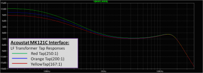
As geraldfryjr mentioned, selecting different primary turns changes the step-up ratio.
In the case of the MK121C LF transformer:
Red tap = 250:1
Orange tap = 200:1
Yellow tap = 167:1
This changes the level of the bass relative to the mids and highs. The step-up ratio of the mids and highs remains fixed at the 60:1 of the HF transformer. The mixer resistors(50K) and capacitors(0.01uF) define the frequency at which the transition is made between the HF transformer and the LF transformer.
Attachment #1: Here is a trend plot showing the electrical response of the MK121C interface for the 3 different primary taps. As you can see, the interface provides a nice smooth boost below 1kHz which is exactly what is needed to equalize out the acoustic roll off from dipole cancellation.
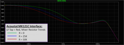
Attachment #2: Here is a trend plot showing the electrical response of the MK121C interface for 3 different mixer resistor values(50K = standard). Notice the bass boost level remains the same, just the frequency at which the transition occurs moves. If you reduce or remove the mixer resistors the boost starts at a higher frequency and you will probably wind up with a mild rise in the midrange...which may or may not be to your liking.
Concerning the Sound Lab Interface:
It may appear that the Sound Lab interface does not have any mixer resistors. However, this isn't exactly the case. If you measure the resistance of the primary winding, you will find it a surprisingly high 3 to 8 ohm depending on the primary tap chosen. If you reflect the 3 ohm resistance thru the 1:200 step-up ratio of this tap on the transformer you will find it is electrically equivalent to using 60K mixer resistors with a low resistance primary(ie almost exactly like the Acoustat). The only difference is that they didn't have to use big power resistors on the secondary side.
The take away point is that running a Sound Lab interface without mixer resistors is electrically more similar to running and Acoustat MK121 interface WITH the 50K mixer resistors than without.
I'm sure this probably isn't the best place to post this information considering the thread is on the CLS.
But I happen to have some plots handy, so here goes...
As geraldfryjr mentioned, selecting different primary turns changes the step-up ratio.
In the case of the MK121C LF transformer:
Red tap = 250:1
Orange tap = 200:1
Yellow tap = 167:1
This changes the level of the bass relative to the mids and highs. The step-up ratio of the mids and highs remains fixed at the 60:1 of the HF transformer. The mixer resistors(50K) and capacitors(0.01uF) define the frequency at which the transition is made between the HF transformer and the LF transformer.
Attachment #1: Here is a trend plot showing the electrical response of the MK121C interface for the 3 different primary taps. As you can see, the interface provides a nice smooth boost below 1kHz which is exactly what is needed to equalize out the acoustic roll off from dipole cancellation.
Attachment #2: Here is a trend plot showing the electrical response of the MK121C interface for 3 different mixer resistor values(50K = standard). Notice the bass boost level remains the same, just the frequency at which the transition occurs moves. If you reduce or remove the mixer resistors the boost starts at a higher frequency and you will probably wind up with a mild rise in the midrange...which may or may not be to your liking.
Concerning the Sound Lab Interface:
It may appear that the Sound Lab interface does not have any mixer resistors. However, this isn't exactly the case. If you measure the resistance of the primary winding, you will find it a surprisingly high 3 to 8 ohm depending on the primary tap chosen. If you reflect the 3 ohm resistance thru the 1:200 step-up ratio of this tap on the transformer you will find it is electrically equivalent to using 60K mixer resistors with a low resistance primary(ie almost exactly like the Acoustat). The only difference is that they didn't have to use big power resistors on the secondary side.
The take away point is that running a Sound Lab interface without mixer resistors is electrically more similar to running and Acoustat MK121 interface WITH the 50K mixer resistors than without.
Attachments
Great info here...I will have to play with those mixer resistors a bit...
Question....I needed to drop the bias voltage a bit on my new CLS panels. I pulled the two diodes and single cap as shown in pic. I chose pulling the front cap/diodes instead of the back by the bias resistor.
The bias appears more like 3,1kv now instead of 5kv. But for some reason interface (bias tranny) is noisier than before pulling the diodes/cap (hum / buzz). I left that first lower cap in, so effectively that first cap value is half the value with a series cap in front. I didn't think it would be a problem...Should I correct it and pull that first cap and tie back into the secondary/ground connection? Any other reason it would buzz with bias reduction?
Attachments
![ACOUSTAT_SCHEMATICS-NO_POT5B15D1[1].jpg](/community/data/attachments/368/368543-e2763e7f330c4581d4782af9cb0c44de.jpg?hash=4nY-fzMMRY)
It would have been easier to just move the Feedpoint of R5 down to the junction of D3 & D4.
Else you also have to short and/or remove C8 as well in order to create a ground connection.
With C8 in there you are essentially modulating the the supply with 60 cycles through C8.
If you want to use a tap that as only one diode down for approx. 4Kv then you have to move the connected ground to the other side of the stack of the multiplier capacitors or else you will get hum as well.
The ground must be taken from the bottom of the same stack of capacitors that the Bias HV is connected to or else you will get hum.
jer 🙂
Question....I needed to drop the bias voltage a bit on my new CLS panels. I pulled the two diodes and single cap as shown in pic. I chose pulling the front cap/diodes instead of the back by the bias resistor....I left that first lower cap in, so effectively that first cap value is half the value with a series cap in front. I didn't think it would be a problem...
You didn't mention it, but did you replace C6 with a jumper? (ie so the junction of C7 & D3 are connected to the HV transformer)
I agree, I would not think effectively reducing the first cap value by half should be a problem. Unless of course there is considerable leakage current. Do you have your neon bulb charge indicators hooked up? If so, what is their flash rate.
Also, is the hum/buzz there even when no amplifier is hooked up?
BTW, the schematic you posted has an error, R2(15ohm) should be across the transformer primary rather than across the capacitors.
More details on this starting in post#14 thru #19 here:
http://www.diyaudio.com/forums/planars-exotics/192497-acoustat-3-mk121c-2.html#post2645383
"I left that first lower cap in, so effectively that first cap value is half the value with a series cap in front."
Oops , Some how I missed this part sorry for the confusion!!! 😉
I don't think that this would be a problem either unless there is excessive leakage as mentioned.
Some how I had it pictured in my mind that both ends of the multiplier was fed through capacitors.
jer 🙂
Oops , Some how I missed this part sorry for the confusion!!! 😉
I don't think that this would be a problem either unless there is excessive leakage as mentioned.
Some how I had it pictured in my mind that both ends of the multiplier was fed through capacitors.
jer 🙂
Last edited:
- Status
- Not open for further replies.
- Home
- Loudspeakers
- Planars & Exotics
- Open CLS II stators - the best way to do it?