Hi,
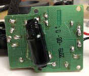
I have the tiny polk blackstone satellite speaker. It measures open at the speaker terminals instead of 4-5ohms.
I scraped the pcb and resoldered each joint. If I do continuity from point to point, it makes connection except at the speaker terminals.
Both the tweeter and the woofer are good.
There are 3 caps, 3.3uf, 18uf, 300uf. If faulty, would it show open at the speaker terminals(amp side)?
Probably take you few seconds to figure it out. 🙂
Attachments
Maybe that large cap is open circuit. Measure the input resistance of the crossover, while shorting that cap's terminals.
Last edited:
Hi,Maybe that large cap is open circuit. Measure the input resistance of the crossover, while shorting that cap's terminals.
While ohm meter is on crossover input, I shorted the 300uf cap, it measured 4 ohm. Heard a popping noise out of the speaker.
I unsoldered the 300uf cap, it seems to measure resistance building up, like the cap is charging, not sure if these means the cap is still good.
I have only a 1000uF polarized cap here. I touched it on the 300uF non polar pcb pads, it made popping noise out of the speaker but still
no 4ohm at the cross over input.
I could draw out the connections between parts tomorrow. Too drowsy now.
Thanks for the quick reply. 🙂
I think this is how it’s wire.Then it seems ok.
Draw out the crossover and post it here.
There aren't too many possibilities.
Attachments
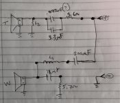
The 300µF capacitor in series with the woofer is a high pass filter to prevent over-excursion of the cone from too much deep bass, which would otherwise destroy the tiny woofer. For a nominal 4Ω driver the crossover frequency will be ~130 Hz. This capacitor blocks DC so a multimeter measuring ohms will read open circuit, and that is normal and what you expect to read.
L1 is the low pass crossover element forming a nominal 1st order slope of -6dB per octave above the crossover. The 18µF in series with 5.7Ω resistor shunts the rising impedance of the bass driver voice coil self inductance to correct the bass driver's rise in impedance as frequency rises which would otherwise prevent L1 from achieving the desired low frequency rolloff to the bass driver.
The 3.3µF capacitor is the first section high pass element for the tweeter, and L2 is the second section high pass element, making it a nominal second order (12dB per octave) slope, and the 3.6Ω resistor attenuates the tweeter level to match the bass driver.
Measure continuity from both terminals of the 300uF to the + input post.
If you get continuity to just one of the 300uF terminals, that is ok.
Measure continuity from both terminals of the 300uF to both terminals of the inductor.
If you get continuity to only one 300uF terminal, that is ok.
Measure continuity from woofer + terminal to both terminals of the L1 inductor.
If you get continuity to both, that is ok.
Measure from woofer - terminal to the - input post. If you get continuity, that is ok.
Bear in mind that this crossover uses a series capacitor on both the woofer and tweeter,
so there will be no continuity across the speaker system input terminals.
Last edited:
Thank you both so much.
I had assumed it would always measure some resistance between 4-8 ohms but not in this case.
I will try what you said and see how it goes.
I had assumed it would always measure some resistance between 4-8 ohms but not in this case.
I will try what you said and see how it goes.
Are you getting sound out of the drivers? If so, probably the crossover is ok.
A few special speaker designs (KEF, etc.) do have a series capacitor on the woofer.
In this case the driver is really a midrange unit anyway, and does need one for that reason.
A few special speaker designs (KEF, etc.) do have a series capacitor on the woofer.
In this case the driver is really a midrange unit anyway, and does need one for that reason.
Last edited:
You can bypass that 300uF and remeasure for a 4-8 ohm DC resistance.
Might simplify things.
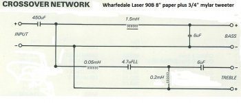
The idea of the 300uF is it gets better bass out of an undersize closed box, in fact.
As in the Wharfedale Laser 90B:
https://www.diyaudio.com/community/...-minor-classic-imo.314732/page-2#post-5431294
Might simplify things.
The idea of the 300uF is it gets better bass out of an undersize closed box, in fact.
As in the Wharfedale Laser 90B:
https://www.diyaudio.com/community/...-minor-classic-imo.314732/page-2#post-5431294
There is no DC path in your schematic You will see the caps charge up with ohm meter. Do your speakers work?
You didn’t kill that tweeter by applying the discharge of the 1000uF cap now, did you? Unlikely but not impossible…
- Home
- Loudspeakers
- Multi-Way
- Open circuit on 2 way crossover, troubleshoot help please.