Hi all
I have a question with regards to an opamp feeding a volume control feeding an opamp again.
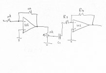
What is the min resistance I can use for R3 if the preceding 10k pot value is a given.
Is it in any way determined by the value of the 10k volume pot?
The attached circuit is in no way the actual circuit in use, but just a quick drawing I made to get my question across.
Sorry for the jpeg.
Thanks.
I have a question with regards to an opamp feeding a volume control feeding an opamp again.
What is the min resistance I can use for R3 if the preceding 10k pot value is a given.
Is it in any way determined by the value of the 10k volume pot?
The attached circuit is in no way the actual circuit in use, but just a quick drawing I made to get my question across.
Sorry for the jpeg.
Thanks.
Attachments
What is the min resistance I can use for R3 if the preceding 10k pot value is a given.
Use 10k linear potz and 2k R3.
Drop decouple cap.
You’ll pick pretty and much more precise log scale.

That is quite an interesting question actually because the inverting configuration means R1 appears as a grounded load to the pot which will modify its law. Get the values right and you could use a linear pot and end up with a fake log law.
As for loading, you have a 10k already in place and so I'd say around 3k3 for opamps like the TL07x series and 1k for 5532's and the like.
The resistor will appear in parallel with the pot at maximum volume which is the determining factor.
As for loading, you have a 10k already in place and so I'd say around 3k3 for opamps like the TL07x series and 1k for 5532's and the like.
The resistor will appear in parallel with the pot at maximum volume which is the determining factor.
Drop decouple cap.
Without coupling capacitor, make very sure it is not a carbon potmeter, as any DC offset or bias current drawn out of a carbon potmeter's wiper will slowly anodize the wiper and eventually cause poor contact (but a small DC current flowing into the wiper is no problem).
I cannot see the point of U1 apart from phase inversion. The input impedance is still 10k, same as with a pot in front.
Double the amount of silicon in the signal path should come with some additional payout.
Double the amount of silicon in the signal path should come with some additional payout.
I cannot see the point of U1 apart from phase inversion. The input impedance is still 10k, same as with a pot in front.
Yup, it must be redrawn as differential receiver with something like or better 0,1% tolerance resistances.

Hi all
I have a question with regards to an opamp feeding a volume control feeding an opamp again.
What is the min resistance I can use for R3 if the preceding 10k pot value is a given.
Is it in any way determined by the value of the 10k volume pot?
The attached circuit is in no way the actual circuit in use, but just a quick drawing I made to get my question across.
Sorry for the jpeg.
Thanks.
Why not connect the pot to the +input of U2 and ground R3? That makes the load on the pot large so you are free to chose one. It also makes the two stages net non-inverting.
As drawn this doesn't make much sense.
You probably don't need the coupling cap either.
Jan
Perhaps erroneously i assumed the OP prefers inverting opamp stages as these tend to sound better.
Why should an inverting opamp stage tend to sound better than an non inverting one? What is meant with 'better'?
Best regards!
Best regards!
Why should an inverting opamp stage tend to sound better than an non inverting one? What is meant with 'better'?
Best regards!
An inverting stage does not have common mode input signal. BJT input opamps can have common mode distortion; FET input much less. Whether it is significant depends on a lot of things, but with low levels like here, and a good opamp I wouldn't give that any priority.
There are lots of amps with non-inverting stages that sound just fine.
Jan
What is meant with 'better'?
This is often a hard question, but luckily not this time 🙂
Around 1985 i wanted to design a phono pre using opamps which will beat my factory made discrete phono. Turned out to be a really frustrating exercise. The best opamps i could get at the time were 5534 and after months of frustration i conducted a simple experiment.
Set up a 5534 as a non inverting amp for a gain of around 10 into a high impedance load. A fixed attenuator at input adjusted the overall gain for unity. This made it possible to evaluate the opamp against a bypass. And it sounded nothing like the bypass. A bit of research led me to the inverting mode and a bit more research led to setting the impedances on both inputs to be equal. And voila it sounded good. Not quite like the bypass but very close.
Today there are much better opamps and the differences are not so dramatic but even so the inverting topology often sounds a bit better. Unsurpsingly, many are unconvinced or unwilling/uninterested to listen.
Why should an inverting opamp stage tend to sound better than an non inverting one?
Because common mode error are nonlinear with common mode itself.
a bit more research led to setting the impedances on both inputs to be equal
Clearly! Input bias currents must provide equal bias voltages at both inputs.
- Status
- Not open for further replies.
- Home
- Source & Line
- Analog Line Level
- Opamp + volume control question.