Hi, friends!
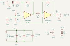
I'm trying to make a simple preamplifier for a dynamic microphone. The microphone has an impedance of 600 Ohms and a frequency range of 50-15000 Hz. The power supply will be single-polar, 5 V, from a regular smartphone charger. The gain will be fixed, 100 times.
The microphone and preamplifier will be used with a simple mixer in a karaoke system.
My questions:
1) Will the input impedance of the amplifier be too low with R1 = 4.7k?
2) Are capacitors C1 and C3 necessary?
3) Is it worth adding inductance to the power supply filtering circuit (and what is its optimal value)?
4) What else can be improved/changed?
Attachments
Last edited:
1) No, in fact, many microphone preamplifiers have an input impedance of 2 kohm.
2) Yes.
3) Insufficient data for a meaningful answer.
4) The noise floor is dominated by thermal noise of R1. You could reduce it a bit by using 2.2 kohm, 22 kohm and 4.7 uF rather than 4.7 kohm, 47 kohm and 2.2 uF for R1, R2 and C1, or reduce it more by going for a non-inverting configuration with a much-lower-impedance feedback network.
Regarding 3), it depends on how clean or how dirty the supply is, at what frequency supply ripple occurs and assuming it is ultrasonic, on whether the output signal will pass through an ADC with a poor anti-aliasing filter that could alias ultrasonic ripple to audible tones. Not having any information on this, I would just add a small 100 uH inductor and hope for the best.

Hello!
My comments:
1) 4.7k should be ok. But you have the option of lowering or increasing input impedance at your choice, by just changing R1 and R2 and keeping the same gain. You can test if 4.7k is too low. In general lower impedance reduce higher frequencies. If this is the case, you can increase R1 to 10k and R2 to 100k.
2) Sure yes, there will be 2.5V DC at these points that must be isolated by the caps.
3) I would insert a 47ohm in series with the power supply. Together with C4 and C6 capacitors (no need of C5), it will create a low frequency pass filter. This opamp drains 6mA typical. You are going to loose 0.006*47=0.3V but this doesn't mean much in this pre-amp.
4) Ra, Rb and C2 are key elemets to affect noise from the power supply. I would increase C2 to 10uF or even higher if this power supply has some low frequency ripple.
In addition, I would add 2 diodes (1N4148) at the mic input to avoid any electrostatic voltage spike during connect/disconnet the mic. Diodes will limit input to -0.6V to +5.6V.
You could include an adjustable gain in the first stage by making R2 a trimpot (varying from 4.7k to 47k), if you think there is a possibility of signal saturation (mic output > 25mVpeak).
Many thanks to all!
My new questions:
1. What type best for C2? Polypropylene or electrolyte?
2. For C4? Polypropylene or ceramic?
3. Will changing values for Ra, Rb affect noise?
Thanks again!
My new questions:
1. What type best for C2? Polypropylene or electrolyte?
2. For C4? Polypropylene or ceramic?
3. Will changing values for Ra, Rb affect noise?
Thanks again!
Hi!
1) If you increase C2 to 10uF, you can use electrolytic - there are people that don't like. I don't see much difference.
2) I would go with a film capacitor for C4 (poliester which is easy to find and cheap at least where I live)
3) Ra and Rb will be AC shorted by C2 so they should not affect noise.
Noise is affected by R1 and R2 - the lower the better S/N. Here it's a compromise between input impedance and noise. You have to choose the optimal topology. Or you can reevaluated the inverting configuration as mentioned by Marcel.
In terms of noise, you need to evaluate how low-noise you need for this application.
Are you going to firstly build this in a protoboard? If yes, it's a good idea to evaluate the pre-amp with your microphone and tests input impedance, capacitors, noise, try other topologies etc. You'll get your own opinion about all the suggestions.
Many thanks to all!
My new questions:
1. What type best for C2? Polypropylene or electrolyte?
ron68's idea to replace C2 with a 10 uF electrolytic capacitor is a good one. With 0.22 uF, the thermal noise of Ra and Rb still has an effect at low audio frequencies (where your ears aren't very sensitive anyway), with 10 uF, the thermal noise of Ra and Rb is suppressed quite well at all audio frequencies.
2. For C4? Polypropylene or ceramic?
I would choose class 2 ceramic (such as X7R) here, supply decoupling is the one thing they are good for. Polyester (such as MKT) is also fine.
3. Will changing values for Ra, Rb affect noise?
Thanks again!
Not when the value of C2 is large enough.
For C1 and C3, avoid class 2 (and class 3) ceramic capacitors. Anything else should work fine. Polypropylene is the best, but the differences are extremely small.
If the preamplifier has to drive a cable, put a 100 ohm resistor in series with C3 for stability.
Last edited:
Sorry, friends!
One more question:
Should I connect Rb to GNDS (signal ground) or to GND (power ground)?
One more question:
Should I connect Rb to GNDS (signal ground) or to GND (power ground)?
Hi! I didn't noticed that there were 2 GND's.
You need a single GND otherwise any difference between GND's will be amplified and be present in the output.
Why did you create this differentiation in GND?
You need a single GND otherwise any difference between GND's will be amplified and be present in the output.
Why did you create this differentiation in GND?
I thought it is important to separate signal and power grounds. I planned to connect grounds through resistor 1om
This is a pre-amp so I don't see a need for it and you do need same GND across all connections to GND.
If you had a small signal pre-amp circuit and digital circuit or a high current power inverter involved with the same power source that's another story.
Just keep same GND for all connections.
In addition, you may also need to include a ground plane (under the pre-amp PCB) or even a metallic chassis grounded to avoid 60Hz/120Hz (or 50Hz/100Hz depending on country) hum induction.
- Home
- Live Sound
- Instruments and Amps
- opamp based simple dynamic mic pre-amp with fixed gain