I am on the point of building an OPA627/BUF634p pre-amp. I have looked up some old threads and found a lot of useful info, but I am left with a couple of questions:-
1) How many BUF's sound best in a pre-amp. (I experimented with them in a headphone design and found that although TI recommend 3, this seemed to rob the sound of some air - almost a sort of compressing effect) I don't know whether they would produce the same kind of effect, and also whether the extra current would make much (or any) difference in a pre?
2) What about biasing OPA627's with a resistor? I have tried this with OPA627's on their own and liked the effect, but has anyone tried it both ways in a pre-amp with BUF634's? Carlos, perhaps?
3) Out here in the sticks, I can only get stripboard to build on. I have been through so much of the stuff it is sickening. (bits of circuit lying all over the place!) Before I waste any more board (and components), does anyone have any useful hints on working with stripboard for this kind of project?
4) One of my biggest headaches so far has been with grounding. I have even gone so far as to build a circuit with a separate wire for each possible ground (power ground, signal ground, left, right, op-amps, buffers) You can probably imagine what it looked like. You could hardly see the components under the forest of wires. My idea was to try joining them up in diffeerent combinations to see what brought about the best result. Well, it was a disaster. Not only did I learn nothing from it, I couldn't even get it to play music at all!
So please, any useful advice will be welcomed.
Thanks in anticipation,
William.
Strip Board
Hi William,
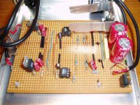
It's a wee prob trying to use strip board for this circuit, but you can obtain a reasonbly good looking design.
If you use the 100 by 150 board as iv'e done, and use the first four central strips for ground. Then i placed the regs on the outer edges for the power , well that's just one method i used , may not be the best. Then used zero link's and some cat 5 aswell.
Hope the attatched image say's more..
The large heatsink on the pos reg is due to a small prob that not even a electronic buff could work out ! Well not visually anyway.
Hi William,
It's a wee prob trying to use strip board for this circuit, but you can obtain a reasonbly good looking design.
If you use the 100 by 150 board as iv'e done, and use the first four central strips for ground. Then i placed the regs on the outer edges for the power , well that's just one method i used , may not be the best. Then used zero link's and some cat 5 aswell.
Hope the attatched image say's more..
The large heatsink on the pos reg is due to a small prob that not even a electronic buff could work out ! Well not visually anyway.
Attachments
Hi there,
I built a opa627 buffer on strip board (the copperless type). I got it about half the size of pete.a 's. No problems with grounding. Two star grounds, one for each channel and then linked at a master star ground. I used basic Zener-transistor regulation, with both channels sharing the rails. I had 47uf of electro caps at the chip pins, bypassed with 1nf film caps, and with the two rails tied with a 0.47uf cap (this made a big difference). Very simple.
Worked perfectly first time and sounds lovely and detailed and smooth.
Some say that a descrete transistor circuit works better than the OPA627. I wouldn't nesscarily disagree.
Shoog
Working with stripboard is a lot easier if you start by "converting" the schematic into a building sketch with the IC's and power rails drawn in first. Then add components to the sketch one by one, use red ink to note where you have to cut the traces (a simple cross will do as well) and where to add jumpers. This will give you an idea of which tracks should be used for power and also how much spacing is necessary to fit everything in. When you've completed the sketch and double-checked to ensure that everything is correct it is quite easy to place components (start with the IC's and the jumpers to your designated power traces) and mostly you'll be able to assemble even complex circuits without mistakes. The "design-phase" of the sketch is of course quite tedious, but if you ask me it's not nearly as tedious as trouble-shooting circuits built on stripboard 🙂hihopes said:3) Out here in the sticks, I can only get stripboard to build on. I have been through so much of the stuff it is sickening. (bits of circuit lying all over the place!) Before I waste any more board (and components), does anyone have any useful hints on working with stripboard for this kind of project?
 Use a 3,5 mm drill bit or a sharp knife to break traces.
 Happy building! 🙂
/U.
hihopes said:
4) One of my biggest headaches so far has been with grounding. I have even gone so far as to build a circuit with a separate wire for each possible ground (power ground, signal ground, left, right, op-amps, buffers) You can probably imagine what it looked like. You could hardly see the components under the forest of wires. My idea was to try joining them up in diffeerent combinations to see what brought about the best result. Well, it was a disaster. Not only did I learn nothing from it, I couldn't even get it to play music at all!
So please, any useful advice will be welcomed.
Thanks in anticipation,
William.
a ground plate shoule be fine.this is my design,the board is carved by a knife
 and leave big copper for ground shadel.finally,its result is very good.
http://www.diyaudio.com/forums/showthread.php?s=&threadid=15403&highlight=digi01
digi
hihopes said:
2) What about biasing OPA627's with a resistor? I have tried this with OPA627's on their own and liked the effect, but has anyone tried it both ways in a pre-amp with BUF634's? Carlos, perhaps?
http://tangentsoft.net/audio/opamp-bias.html
Thanks for all your replies. I will studynthem and answer this evening when I have a bit more time.
OK, now I have a moment.
Firstly, Pete.a, thanks for your pic. I will have a good look at it, but my initial feeling is that I want to build a lot more compact than you.
Hi Shooq, I can't get copperless stripboard, so I am having to make do. Thanks for the useful info. I assume your "master"star ground is to the chassis, (or not)? Are you using a metal or plastic enclosure, and is your chassis connected to ground in any way?
Where exactly did you tie the rails with 0.47uF? I have seen it recommended to tie them across the Vcc pins of the op-amps and was intending to do that, but with much smaller caps (100nF Wima poly).
Hi Nisbeth,
I agree with you about the drawing. I have used Coreldraw to plan my layouts and probably spent a lot more time drawing than soldering.
Digi01, thanks for all the tips and info and especially for the stripboard layout. I had a totally different idea (To place the buffer "above" the opamp in each channel. I never considered placing tham next to each other. Will have a good look at your design. Perhaps after building in stripboard, I will try one like you did by carving. Looks cool!
Thanks for the e-mails Per-Anders and Dr. H.
Per-Anders, thank you, I have had a good look at your QRV04. It looks excellent (as do all your designs I have seen). I can learn some things from it, but it is obviously made for a PCB and surface-mount components rather than for strip-board. The postage alone for one of your PCB's would kill me.
Dr.H, thanks for the very kind offer. Reply sent by e-mail.
BTW, no-one has yet replied to my first question. How many buffers will likely be best? and if more than one per channel, should they be stacked or mounted next to one another for best results?
Hi there,
I assume your "master"star ground is to the chassis, (or not)? Are you using a metal or plastic enclosure, and is your chassis connected to ground in any way?
Its on the strip board. I usually tie my star ground to the output earth on the power inlet, and then take the case ground to that point as well. There is a very good case for isolating the circuit ground from the case ground, in terms of keeping noise out. This can be achieved by making a little bundle of a 100Ohm resistor paralleled with a 0.1uf cap, paralleled to a pair of high power diodes mounted facing in opposite directions. This is placed between the star ground and the power outlet ground. This allows a fault voltage to find case earth whilst isolating the circuit in normal operation. The cap is essential as a path for radio noise to bleed out of the circuit.
Where exactly did you tie the rails with 0.47uF? I have seen it recommended to tie them across the Vcc pins of the op-amps and was intending to do that, but with much smaller caps (100nF Wima poly).
You are right about between the Vcc pins. Theres not a huge differnce between 100nf (o.1uf) and 0.47uf. Its what I had in reasonable quality. Use what you have. In certainly cleaned up the sound significantly. Made it a lot smoother.
Cheer
Shoog
thanks Shoog,
I meant 100pF, not 100uF (I have a few of these and they arte small enough physically to be shoved in between the pins. Do you think I should be looking at a larger value instead?
I meant 100pF, not 100uF (I have a few of these and they arte small enough physically to be shoved in between the pins. Do you think I should be looking at a larger value instead?
I don't have enough range of experience to recommend a definate value, all I can say is that 0.47 worked for me. I dare say 0.1uf would work equally as well.
Shoog
Shoog
Universal unit
Because on this forum are again and again questions about using of some amp with opamp and buffer, I'm getting here this solution. This unit is quite universal for every use ( preamps, line outputs, active cables etc. ) and have excelent parametres : BW up to 1 MHz, SNR over 120 dB ( ref. to 2 V output, A - weighted ), distortion below 0.001 %. Supply voltage may be AC or DC, terminals screwed or square pins. Universal are also op amp's package ( DIL or SOIC ). On PCB you can also to see, how look star ground 😎 . This connection is little changed PMA's " Universal buffer ". All this documentation is FREE and take it, guys, like my present for the X - mas to all. Circuit diagram :
Because on this forum are again and again questions about using of some amp with opamp and buffer, I'm getting here this solution. This unit is quite universal for every use ( preamps, line outputs, active cables etc. ) and have excelent parametres : BW up to 1 MHz, SNR over 120 dB ( ref. to 2 V output, A - weighted ), distortion below 0.001 %. Supply voltage may be AC or DC, terminals screwed or square pins. Universal are also op amp's package ( DIL or SOIC ). On PCB you can also to see, how look star ground 😎 . This connection is little changed PMA's " Universal buffer ". All this documentation is FREE and take it, guys, like my present for the X - mas to all. Circuit diagram :
Attachments
hihopes said:BTW, no-one has yet replied to my first question. How many buffers will likely be best? and if more than one per channel, should they be stacked or mounted next to one another for best results?
I used ZERO buffers with my OPA627BP preamp. It has no trouble driving 15 feet of interconnects or my amplifiers. No noise or grounding problems either (batteries are cool). 😀
An externally hosted image should be here but it was not working when we last tested it.
- Status
- Not open for further replies.
- Home
- Amplifiers
- Chip Amps
- OPA627 preamp