Hi guys,
What do you think of this?
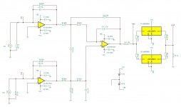
I'm planning to connect it right after my buffalo III. The output will have more LME49600s, in parallel. Probably 6.
What do you think of this?
I'm planning to connect it right after my buffalo III. The output will have more LME49600s, in parallel. Probably 6.
Attachments
Last edited:
what are you driving? - not enough V or V gain for pro audio line out, low sensitivity headphones
for consumer line levels, cable lengths the buffers are unnecessary - and open loop likely add more distortion than the op amps - not that we can tell from the LME49600 datasheet since the device THD # are shown inside a high loop gain op amp feedback loop
for consumer line levels, cable lengths the buffers are unnecessary - and open loop likely add more distortion than the op amps - not that we can tell from the LME49600 datasheet since the device THD # are shown inside a high loop gain op amp feedback loop
Last edited:
Hi jcx,
I was really looking forward to have a reply from you -your nested thread was very interesting!
I'm driving nothing, this will drive my speakers (91db) directly but with 6-10 LMEs at the output!
Unfortunately, I cannot make any sims with TINA-TI, and I don't have the models of those opamps to do sims with LTSpice....
Any advice that you might have for my attempt are most welcome!
Cheers
Edit: If I'm not mistaken one LME can swing easy 17v with 18V supply. And with 6 of those, I got 1,5A.
no the LME buffer isn't that good near the rail the datasheet shows it needing 3.5 V to drive -150 mA - and the table has typical and worst case # reversed - this is about the worst datasheet I've seen in a while from such a big player
you can also use the datasheet table gain/load numbers to get ~ 5 Ohms output R – so the emitter R must 10 – giving 2.5 V drop with 250 mA, then add output Q Vbe...
for a speaker driving "flea power" amp I would try a (or two paralleld) LT1210 1 A output CFA that comes in the easy to heatsink TO-220 in a multiloop - I have used the faster but lower current LT1206 TO-220 in a multiloop prototype
the LT1210 would be a savings on $/A too
Last edited:
Well, I already have the LME49600s so I will play ball with those...
Does anybody have the libraries of the above parts for LTspice?
Does anybody have the libraries of the above parts for LTspice?
Last edited:
the LME buffer is fast enough to put inside the opa164x op amp feedback loop with only a little concern, attention to a few details
using a lot of the LME in parallel you need to look at the load all of the LME input's input C adds up to
and the load sharing R should be much lower value both to keep load C from adding excess phase shift and to not lose any more than the minimum possible of your V supply headroom at max output current
you could even in principle put the buffers inside your 1st schematic's differential to single ended converter/filter feedback loop
Does anybody have the libraries of the above parts for LTspice?
Attached. 🙂
Depending on operating system YMMV on the file location to put them in, but under Windows 7 64-bit the .sub files go in: Program Files (x86) -> LTC -> LTspiceIV -> lib -> sub. The .asy files go in: Program Files (x86) -> LTC -> LTspiceIV -> lib -> sym -> opamps. If you are using a different path you will need to double click each .asy to open them up in LTSPICE, then go to edit -> atributes -> edit attributes and change the path line to correctly point to the .sub files.
Note the OPA1644 is just one amp in the package and also works for the 1641 and 1642 according to the .sub file comments. To make a full OPA1644 just put down four of them and run Vcc and Vee to each.
Be sure to read through TI's comments in the LME49600 .sub file (read it as .txt), there are a number of quirks. Unlike the real chip it won't work for rails less than +/-10Vdc, and unlike the real thing the BW pin can't be left open, has to be connected to Vee through a resistor. The BW resistor values are in figure 22 in the data sheet, 10R to 100K.
If you are running a 64 bit OS like I am the LT Spice files really are all in the 32 bit subsystem. Don't bother asking LT when the 64 bit version of LTSpice will be out. Trust me, just don't.🙂 I had that chat with the fellow at LT maintaining the program and he had a very strong opinion that 64 bit buys absolutely nothing more with the program, at least at this point in time.
Attachments
Last edited:
most don't recommend modifying the LTspice lib files - much better to have your own mylib directory in your documents folder where you keep your .asc - add .include statement, file path to any schematic using the added parts
most of the time you won't need special symbols
the highest portability is to just paste the model .sub into the schematic with the spice directive tool
http://www.diyaudio.com/forums/soli...ain-composite-op-amp-circuits.html#post951110 posts 2 and 3 show the .sub model on the schematic page
most of the time you won't need special symbols
the highest portability is to just paste the model .sub into the schematic with the spice directive tool
http://www.diyaudio.com/forums/soli...ain-composite-op-amp-circuits.html#post951110 posts 2 and 3 show the .sub model on the schematic page
I fried the OPAs......applied inverted ps polarity....Darn, I shouldn't be experimenting at 3am.
I'm going to try with LME49880s until the order arrives.
Weird thing that the caps survived....
I'm going to try with LME49880s until the order arrives.
Weird thing that the caps survived....
Hi Jan,
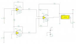
sch2 is a mess, I uploaded an "auto-save" TINA-TI made instead of the schematic I'm actually building.
As for R1&R2, I was trying to do some sims with tina-ti and it was giving me errors. It became quiet when I added those two resistors. Still, I couldn't run the sims. I was never good with sims. I manage basic stuff only with multisim. It seems to be the only app that understands me 🙂
Anyway, I gave that up, strictly bench work now on. If only I had an analyzer.....Soon...
Cheers!
PS: R3 is still there, hooked on the non-inverting inputs, for gain setting.
Last edited:
PS: R3 is still there, hooked on the non-inverting inputs, for gain setting.
I wouldn't think you want that. It does cause xtalk and also decreases what is called noise gain, meaning the I>V doesn't work as accurate anymore. More like as if the opamp has much lower gain.
Jan
Hmm. Yes, indeed I wouldn't want that. I'm still on the build process, haven't tested anything so far.
How would you propose to do it to avoid such issues?
I have to sit down at some point and finally read B.Pease's book.
How would you propose to do it to avoid such issues?
I have to sit down at some point and finally read B.Pease's book.
I decided to make them modular. One board with buffers, one I/V.
The buffer layout is already send to fabrication, I'm working on the I/V stage now. I will actually make both circuits that I posted and see in action what's what.
There is another modularity, I'm making adapters for the I/V board so I can change on the fly opamps.
The buffer layout is already send to fabrication, I'm working on the I/V stage now. I will actually make both circuits that I posted and see in action what's what.
There is another modularity, I'm making adapters for the I/V board so I can change on the fly opamps.
- Status
- Not open for further replies.
- Home
- Amplifiers
- Solid State
- OPA1642&LME49600 IV&