Hi.
I have a few BDW83A/84A power Darlingtons.
Can I use a pair as outputs driven by an op-amp ?
Ultimate hi-fi not required, just a reasonable sound.
Power supply about 35-0-35 (with regulators for the opamp)
What output power can I expect into 4ohm.
Thanks.
Andy
I have a few BDW83A/84A power Darlingtons.
Can I use a pair as outputs driven by an op-amp ?
Ultimate hi-fi not required, just a reasonable sound.
Power supply about 35-0-35 (with regulators for the opamp)
What output power can I expect into 4ohm.
Thanks.
Andy
Hi.
Thanks for the link.
Is the circuit up-to-date or did the comments result in some changes ?
Not what I asked for but I do have an old board I could modify.
Andy
Thanks for the link.
Is the circuit up-to-date or did the comments result in some changes ?
Not what I asked for but I do have an old board I could modify.
Andy
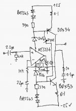
Here is a sketch of a circuit I modelled but did not get around to building. The problem with it is thermal tracking of the quiescent currents. The tracking with dual schottky diodes did not work very well (in spice) so I tried an NTC thermistor which theoretically could do the job. The pot is to set the quiescent current.
Attachments
our friend from turkey
i wonder why you post and drive other people to do a circuit that doesnt work .....
also this amp is so called the john fisher amplifier and its NOT you property to publish in a turkish forum ...
you were also TOLD AND OR ADVICED from many including me in this forum not to mess up with this amplifier since dont really working ....
if you search our post in the back about this only negative things about it .....
the last time we talked i expalin to you that i had trouble with the circuit and if you made an efford to make it work properly we would like to share your comments about it
STILL WAITING !!!!!!!!!!!
The problem with using an opamp frontend is that you are limited by the supply rails of the amp, unless you configure the output stage to have some voltage gain. This has a habit of being unstable.
It's a much better idea to use a discrete front end, in this case.
It's a much better idea to use a discrete front end, in this case.
Re: KAPIBARA YOU LITLE THIEF
Hi Sakis,
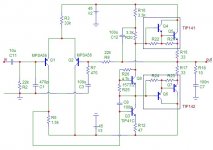
There it should work ok now. I did not like the diodes setting the quescient current and replaced with VBE multiplier. Also changed the VAS emitter resistor to 47 ohm which seemed to balance the current flowing in each output.
sakis said:i apologize to the forum and i am ready to be banned if the moderators decide to
you litle mizerable thief !!!!!very nice off you to present somebody else"s work under the name of diyaudio turkye and kapibara !!!!! this is complete bull***** sheet
shame on you to behave like that .....
i presume that in this forum everybody respect other peoples work
how destroyer x will feel if i take his amp ...post it is a greek forum under my name ???????
you should remove your name from there
give the credit to the one that owns it thats john fisher
and then inform all poor guys that may be want to copy this that this amp is not working properly any way
Hi Sakis,
There it should work ok now. I did not like the diodes setting the quescient current and replaced with VBE multiplier. Also changed the VAS emitter resistor to 47 ohm which seemed to balance the current flowing in each output.
Attachments
Calm down sakis, dont be mad.
Does not any body to steal John Fisher schema.
I'm only draw pcb and layout this schema, like you.
But my pcb and equipment diffrent to your pcb and equipment.
My pcb works, your pcs does not works. Thats is your problem.
Mybe it is not to much quality, but works fine, simple and cheap.
Sorry for the bad English.
Various topologies can be seen here :
http://www.angelfire.com/sd/paulkemble/sound5.html
The oldest I can see using similiar topology is 40W from 1974 RCA.
It uses resistor for feeding differential pair, PNP differential pair without degeneration, NPN VAS, bootstrapped VAS load. Output stage is can be made of darlington and quasi complementary.
30W Bailey topology also uses this bootstrap for loading VAS, but the input is singleton, not differential.
Attachments

i apologize to the forum and i am ready to be banned if the moderators decide to
you litle mizerable thief !!!!!very nice off you to present somebody else"s work under the name of diyaudio turkye and kapibara !!!!! this is complete bull***** sheet
shame on you to behave like that .....
i presume that in this forum everybody respect other peoples work
how destroyer x will feel if i take his amp ...post it is a greek forum under my name ???????
you should remove your name from there
give the credit to the one that owns it thats john fisher
and then inform all poor guys that may be want to copy this that this amp is not working properly any way
Dear Mr.Sakis,
We dont need a new Turkish - Greek war...
First I want to apologise from you. Because I think, in this problem I have some role.
I was the moderator of Turkish DIY site while this posting published first. So I gave the permission to Kapibara for publishing this. In fact I did not explore enough before permissing. I guess the exist moderator will be correct that mistake.
HOWEVER;
I THINK YOUR REACTION IS TOO MUCH FOR THAT ISSUE. YOU CANNOT INSALT ANYBODY FOR ONLY THIS LIKE MATTER. IF YOU CONSIDER, INTERNET IS AN OPEN SOURCE FOR EVERYTHING AND THE DIY AUDIO IS YOUR HOBBY (IS IT?) THEN YOU MAY TOLERATE SOME "STEALS". BUT WITH NOT THIS WAY I THINK.
Thank you for your patience and tolerence in advance..
explaination ....
A) this circuit does nto belong to kapibara ....if create apcb arround it i dont think he can post it as his own work
B) zillion of real experts study this circuit ( and i chalenge more to do so ) and the amp itshelf doesnot really work especially if you feed it with 50+50 volts
C)i dont mind so much that kapibara post that under his name but mostly that he is going to put more people to construct a very wrong thing
D) on the other hand as i previously asked many times kapibara to place his work about this amp in the forum since many constructed but most of the failed including me there was never one answer from him ......MEANING that probably the amp was never working properly
E) kapibara .....my pcb was made more or less tha same way but were i come from we use signal genarators ociloscopes and distortion analyzers to take a basic look how one amplifier works and the results were just terible .....but yes ok as you said its a cheap simple thing but i wonder how cheap this is going to be when the guy who constructed after your direction will blow a pair of expensive speakers....... Even a picture of the amp is stallen from john fishers site .......look at your pictures p transitor is mounted on other heatsink than n ?????????thats thermal runaway guarranty !!!!!!!!
finaly i have no problem with op amp driving darligtons but somebody has to design it properly ( not me ) Also very posssible for the john fisher amp to work better with a bit here and a bit there
thats it !!! sakis
Dear Sakis,
I dont want to be the advocate of Kapibara.
To make a PCB on a circuit doesnt give you a right to write your name on it. Were absolutely agree.
However, Kapibara already made some modifications on that circuit. Not only PCB design!
- First; the output darlingtons has changed by himself.
- Second; the LTP BJTs replaced with a higher voltage ones by himself.
- Third; the NFB line is modified, gain is reduced and a frequency compensation is added by himself.
May be you will say "thats all?". May be its not enough to say "my project".. But at least its a step for a novice diyer. What do you say?
And a final note: As I remember Kapibara burns a lot of component at this work. So the modifications are because of these burnings. And youre right, with this configuration, thermal runaway is a destiny.
I think this is a good example for op-amp driving darlingtons.
http://sound.westhost.com/project76.htm
But thermal runaway risk is still exist..
http://sound.westhost.com/project76.htm
But thermal runaway risk is still exist..
Cannot believe the controversy stirred up by such an apparently simple question!
Nico Ras's tweak now makes the circuit very similar to the Velleman K8060 kit which has been discussed at length in various threads on here.
If you do a search for that on here you will get all the info you need.
I think the low risk approach is to use the devices in a K8060 clone as the devices seem a good substitute for the TIP142/147.
The K8060 design has frequency compensation capacitors liberally sprinkled over it which is not a good sign but it obviously works.
You have the suffix A which means low voltage so I would limit the supplies to 25-0-25.
Jaycee The zener diodes in my circuit can be altered to suit any supply,
but since I have not built it, I hesitate to recommend it. The main issue would be thermal runaway.
Hi all,
I am not a moderator of any sorts but an electronic engineer by profession with close to 40 years experience. I would like to comment that there is relatively little new in the form of analogue audio.
I would guess that about everything and anything has been done by someone, somewhere, sometime. I do many designs that I claim as my own. However, in reality very little is my own. It has either been taught through first principles durin my studies. Picked up from reverse engineering, saw somewhere and remembered it, whatever.
I would agree with you that if you copied and pasted someone elses work then that is not nice, but if you did a bit of homework on the subject, found some way to better it, changes something, or the like there is nothing in this world that is that sacred anyway.
I often use ideas from one designed, mix it with that of another designer tweeak it and find ways to improve the sum of the results - now I spend much time on this and do I claim it as my own. Heck why not, it was my effort that got the result that I wanted - not so?
I have a "Krell clone" and it is my own. There is nothing new about full complementary symetry, it has been around since the late seventies, before Dan Augustino (designer and president of Krell) even knew the Krell company would ever exist.
I made a very small change to this amplifier, something I researched for several months and this improved the slew rate as well is improved THD by several orders of magnitude over the original design.
Is this my design. Of course it is! Do I call it a Krell, not on your life that belongs to Dan- Also it is better.😀
niko....
i am with you 100% most of us work this way
this forum is so nice but some times information come from opinion and not from construction.....that can create problems
i give you small example of what i say and you will understand ....
kapibara's work on the tr forum is actually very nice nice foto well presented schematic ....so some kid or grown up see the circuit copy the pcb ( also very nice work ) go buy the parts and go ahead on construction ....
so he go to a shop and buy one tip 142 and one tip 147 to make the amp.
well ...... one very importand trick about these darligtons is that its not enough to have one of them ..... it has to be same brand and even same serial .....not trully because matching and things like that but mostly because darligtons from other factory may have diferent resistors between the driver and output transistor depending of the specs of the costumer who originaly ordered to the manufacturer
thats the bigest reason why most designs from elector using bdv66-67 ( philips version of tip142-147 ) tip 142-147 elector amps using bdw23-84 eventually failed ...... and actually failed and given up after somebody tryied to repair them......
in this amp if you have tip 147 from philips and tip 142 from st you are doomed .....
see what i mean ???? missing information .....
belive there is a hell of a lot others missing
also i cannot read turkish and i think that kapibara recomends a 50+50 volts rail ..... to this amp ??????
idle ....ocilation , SOA and so many other issues should be considerd before construction
friendly regards sakis
Re: explaination ....
Dear Sakis,
If you are so sure that this design is by John Fisher and it is rubbish, then why blame kapibara, why not John Fisher.
There are no rules why output transistors cannot be placed on separate heatsinks.
Also if you are running such high voltages (+-50V) and know that it would get very hot, especially if heatsinks are under sized the diodes should be placed on the heatsink to track the temperature. If paced on the PCB it will track the ambient and you are cruising for disaster.
The diodes will work but the Vbe multiplier is better. On the other hand the diodes will work well if you replace the TIPs with lateral MOSFETs such as 2SK1068 and 2SJ182.
Why don't you try this (you may have to use only two diodes else the quescient current will be very high) and if it sounds and measures nicely, then you can publish it here as your own design.
Kind regards
Nico
sakis said:B) zillion of real experts study this circuit ( and i chalenge more to do so ) and the amp itshelf doesnot really work especially if you feed it with 50+50 volts
C)i dont mind so much that kapibara post that under his name but mostly that he is going to put more people to construct a very wrong thing
thats it !!! sakis
Dear Sakis,
If you are so sure that this design is by John Fisher and it is rubbish, then why blame kapibara, why not John Fisher.
There are no rules why output transistors cannot be placed on separate heatsinks.
Also if you are running such high voltages (+-50V) and know that it would get very hot, especially if heatsinks are under sized the diodes should be placed on the heatsink to track the temperature. If paced on the PCB it will track the ambient and you are cruising for disaster.
The diodes will work but the Vbe multiplier is better. On the other hand the diodes will work well if you replace the TIPs with lateral MOSFETs such as 2SK1068 and 2SJ182.
Why don't you try this (you may have to use only two diodes else the quescient current will be very high) and if it sounds and measures nicely, then you can publish it here as your own design.
Kind regards
Nico
keep in mind
that all these things were said to kapibara before ...i think a year ago or less ....
also with 50+50 rails you should expect from this amp arround 110-120w @ 8R ...what ???? coming from only 2 transistors ????
no way hosse 😀 😀 😀
i am not really upset about kabibara who posted john fisher schematic like it belongs to him .....
i am mostly upset cause people are going to see this and try to construct and then they are going to be so pissed off and never going to bothered to tell us about their work in the forum ....
i rest my case ...thank you
that all these things were said to kapibara before ...i think a year ago or less ....
also with 50+50 rails you should expect from this amp arround 110-120w @ 8R ...what ????
coming from only 2 transistors ????no way hosse 😀 😀 😀
i am not really upset about kabibara who posted john fisher schematic like it belongs to him .....
i am mostly upset cause people are going to see this and try to construct and then they are going to be so pissed off and never going to bothered to tell us about their work in the forum ....
i rest my case ...thank you
- Status
- Not open for further replies.
- Home
- Amplifiers
- Solid State
- OP amp driving BDW83A/84A