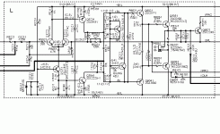
This is one of the seven power stages of a budget Onkyo AV receiver (TX-SR504E). Pretty conventional topology, nice choice of transistor and not too much open loop gain. I would probably use emitter degeneration on the input pair and either buffer or cascode the VAS, but that is a different story.
My question is about the output configuration. An undivided 82 R resistor is used between the emitters of the predrivers, which is nice, but it is paralleled by capacitor, which I think I have never seen before.
The purpose of the undivided resistor is to be able to be able to shift bias voltage from the non-active output base to the active base. If no cap is used, the total voltage between the bases of the output pair can also increase if the active transistor needs a high input current. With a capacitor in place, this is no longer possible. Why would one want to do this?
Attachments
Self explains it all. He calls it emitter follower type II.
The purpose of the shared resistor is to allow the base to be reversed biased for faster turn-off. The cap I don't quite recall it's purpose or if he recommended for or against it. I have a feeling he recommended for it.
The purpose of the shared resistor is to allow the base to be reversed biased for faster turn-off. The cap I don't quite recall it's purpose or if he recommended for or against it. I have a feeling he recommended for it.
Yes, I just reread that (it's been too many years). He does recommend a 1 µF film capacitor to speed up the switch-off. Maybe this small value is a compromise that still gives the improvement at HF but also the benefit of higher drive voltage at low impedance loads at lower frequency.
I just did the bias calculations. The input pair has a current imbalance of 7 - 10%, depending on what you would want to assume for V_BE. Just changing R5114 to 932 R (910 + 22) would drop that into the 1% range!
I just did the bias calculations. The input pair has a current imbalance of 7 - 10%, depending on what you would want to assume for V_BE. Just changing R5114 to 932 R (910 + 22) would drop that into the 1% range!
That capacitor is used to speed upthe turnoff and helps in fast recovery during clipping, if you remove it, the amp would sound crackle when pushed to clipping...Try it!
Leach says the capacitor does no speeding up, but his argument is not quite clear to me. Assume the amp is being driven hard towards the positive side, so the upper driver draws more current than it would in idle. If there is a cap, it is going to clear out the lower output transistors base, too.
- Status
- Not open for further replies.
