hi
I have a 2x21V transformer and I am wondering if I could use a doubler and simpe rectifier in paralel to get -30V.0V.30V and
-60V.0V.60V
help please!!!
I have a 2x21V transformer and I am wondering if I could use a doubler and simpe rectifier in paralel to get -30V.0V.30V and
-60V.0V.60V
help please!!!
Probably not the best solution, but considering what you have, yes, this will work fine. Just remember to observe the power ratings on the transformer and filter the DC well.
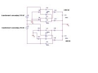
can I run the doubler like in the schematic?
what voltage should be caps rated?
what polarity?
any advice VERY appreciated
regards
what voltage should be caps rated?
what polarity?
any advice VERY appreciated
regards
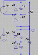
darkfenriz, your schematic is so complicated that I confused myself looking at it 🙂 Another proposed idea has the best diode quantity but disadvantage of half-period rectification on both +/-30V and +/-60V (and 50Hz ripple is more difficult to filter out than 100Hz), besides, you noticed it, separate windings. Why not using classical variant, see attachment. there you will have 100Hz ripple at +/-30V thus suitable for high power, and 50Hz ripple doubler at +/-60V. Capacitors C1, C2, C3, C5 work at 30V, and C4, C6 at 60V. Hope I've been helpful.
Attachments
another idea 🙂
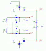
darkfenriz, I was thinking that maybe you need this supply for G-class amplifier, so high power would be needed from both +/-30V and +/-60V. Then I made some modification to that schematic so now you can have full-wave rectification for all voltages 🙂 , see attached image.
[and off this topic] - is that you who proposed somewhere at this forum to hear the difference between original audio file and IMD-deliberately distorted (with DSP processing) copy. I was interested in this and then could't find that thread again. If that were you then may I send you my audio file for such processing?
Attachments
hmmm... not quite that, darkfenriz.
There was a simple talk about IMD influence on sound character, without any math. I recall like you proposed there to add about 0,1% IMD and compare with original sound.
There was a simple talk about IMD influence on sound character, without any math. I recall like you proposed there to add about 0,1% IMD and compare with original sound.
darkfenriz said:it couldn't have been me
thanks for your input and teaching me some lessons
cheers
czeϾ
a mo¿e majstrujesz hybrydê ze stron TCJ by John Broskie?
For smaller currents it's OK to use some voltage doubler but not for a power amp.darkfenriz said:hi
I have a 2x21V transformer and I am wondering if I could use a doubler and simpe rectifier in paralel to get -30V.0V.30V and
-60V.0V.60V
help please!!!
A voltage doubler is a really hard application for the caps and the transformer and it produces lot's of unnecessary reactive power => only heat.
My advice is to get a suitable transformer and make a conventional power supply.
To peranders: your statement is absolutely valid for half-wave rectification circuit which is usual case of voltage doubler rectifier like my first posted schematic in this thread. I mentioned that it's not suitable for high power application eg. amplifier output stage, this is widely known fact.
My second schematic here represents full-wave rectification for all output voltages. I think that transformer operation in this case is absolutely the same as in usual single-bridge rectifier, certainly with a transformer momentary and average currents doubled in regard to high rails +/-60V comparing to +/-30V. You can try to simulate transformer operation in such circuit and reveal this.
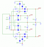
I just reviewed again the first schematic by darkfenriz and found it is the same full-wave rectifier with the exception of higher losses - 3 diodes in series for each half-wave instead of two possible.
Anyway I agree that these circuits are too complicated and good to use only in case when one cannot have the needed secondary windings.
My second schematic here represents full-wave rectification for all output voltages. I think that transformer operation in this case is absolutely the same as in usual single-bridge rectifier, certainly with a transformer momentary and average currents doubled in regard to high rails +/-60V comparing to +/-30V. You can try to simulate transformer operation in such circuit and reveal this.
I just reviewed again the first schematic by darkfenriz and found it is the same full-wave rectifier with the exception of higher losses - 3 diodes in series for each half-wave instead of two possible.
Anyway I agree that these circuits are too complicated and good to use only in case when one cannot have the needed secondary windings.
- Status
- Not open for further replies.
- Home
- Amplifiers
- Power Supplies
- one trafo->doubler+rectifier paralel?