Hello Everyone 👋
- I have my friends car amplifier and it came to me with gain potentiometer damaged and one channel was pulsing.
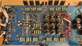
- Fixed the potentiometer changed 2 transistors "marked photo" and now i found that the output transistors are getting hot, slightly lower amplitude than the other channel "could be the potentiometer that i fixed ?"
- I would like some help/guidance troubleshooting the issue.
Attachments

Pulled them out and they tested shorted, yes i replaced one like for like and the other i have found a suggestion by Perry Babin "D1302 with 2N3904".
Okay, no Ebay parts - right? All current manufacture at the time you purchased them? Old 2N3904 is fine as long as it is really a 2N3904.
So since the behaviour changed, something changed and that would be anything you did. I would check very carefully that you installed the transistors the right way and that the pinout was the same. JEDEC transistors normally have the base in the middle, Japanese (JIS) and Proelectron types are most often on one end with collector in the middle. Sometimes the order is swapped as well, so ECB instead of BCE.
So since the behaviour changed, something changed and that would be anything you did. I would check very carefully that you installed the transistors the right way and that the pinout was the same. JEDEC transistors normally have the base in the middle, Japanese (JIS) and Proelectron types are most often on one end with collector in the middle. Sometimes the order is swapped as well, so ECB instead of BCE.
Bought them on mouser, i would like to mention that the channel didn't work when brought to me.
I have traced to them 2 transistors, now works but gets hot
I have traced to them 2 transistors, now works but gets hot
 Moved to Car Audio
-One in particular on the positive side gets hot quicker than others, but all of them get warm.
-I connected one channel at the time to a small 8ohm speaker "is what i have" with the gain at minimum.
-Starts with 1.5 amps once starts heating starts drawing more claiming 3+ amp
-I connected one channel at the time to a small 8ohm speaker "is what i have" with the gain at minimum.
-Starts with 1.5 amps once starts heating starts drawing more claiming 3+ amp
Without being clamped to the heatsink, with biasing (working in class AB), you can expect the idle current to avalanche.
Without knowing if the amp can drive a load symmetrically to clipping, it's hard to know the condition of the amplifier channel.
Without bias pots, it's likely supposed to be a class B (there are exceptions). What's the DCV across the emitter resistors in the other channel?
Did you (or anyone) replace any other transistors in the amp?

Okay, so with the board mounted in the chassis / heat sink and transistors mounted, measure the drop across the emitter resistors (bias current) with no speakers connected. Also measure the DC offset for each channel (speaker output to common).
If the outputs are not mounted properly, they absolutely will go into thermal runaway.
If you measure high bias current on the "bad channel", most likely the bias circuit is damaged or needs adjustment (fixed resistors). Other faults can cause this as well. A schematic at this point might be really helpful.
Okay, all output transistors are back on the board, across emitter resistors 1.4v on the bad channel and 0.1 on the good one, no signal imput, no speakers, gain set to minimum.
At the speaker terminal i have 19.7 mV on the bad one and 0.5 mV on the good one.
Good channel stone could, bad channel warming up slowly.
Board still not mounted on the heat sink ( I am watching the amps and i shutdown while measuring)
The amplifier had some work done in the past In the power supply section, amplifier section appeared untouched.
Thanks everyone for your help so far, let me know if is anything i can measure/compare. 🤗
Okay, so your bias or driver sections may have a problem. This can also be caused by some types of voltage amplification stage that drives the bias core. Your DC offset measurements show the voltage amp section is working, I suspect a bias circuit or driver problem. There are usually resistors between the drivers and predrivers (if those exist). If they go open or have a bad solder connection you will also have very high bias current. I would check Q107, Q108 and the bias Q109. Any open circuit in Q109 will result in high bias. It looks like you have a thermistor sensing internal case temperature as well.
What is the value of the emitter resistors? They look like 0.47R.
What is the make and model, I may have missed it. It's always good to check and make sure it isn't oscillating as that can draw huge amounts of current.
What is the value of the emitter resistors? They look like 0.47R.
What is the make and model, I may have missed it. It's always good to check and make sure it isn't oscillating as that can draw huge amounts of current.
Yes they are 0.47R.
Amplifier make is "Carpower VORTEX-2/600".
I will check resistors R128, R129, R130, they may have drifted in value.
Amplifier make is "Carpower VORTEX-2/600".
I will check resistors R128, R129, R130, they may have drifted in value.
Hi Valx,
Have you searched for a service manual? A schematic would really help to get you accurate information.
Have you searched for a service manual? A schematic would really help to get you accurate information.
Hi anatech 👋
I have looked previously with no success, I doubt that i will find a schematic for this amplifier being fairly old model and not popular.
I have looked previously with no success, I doubt that i will find a schematic for this amplifier being fairly old model and not popular.
Okay, no problem ....
You have high bias current, so let's go back to amplifier basics. I don't know if you have a variable, bipolar power supply. This is what I would use for troubleshooting as it makes things a lot easier and you can run things at lower voltages for troubleshooting. You won't have to run the main inverter and can test at lower voltages where things don't heat up.
Measure resistors between the bases of pre-drivers or those and the output foil. If open, you can have this situation. If those are okay, apply power and measure emitter - base voltage drops on the drivers and transistors before that. Expect high voltages compared to normal, if you see zero or negative you'll be close to the problem. You have already checked the outputs so we will assume they are all okay.
Okay... i have to apologise to anatech for not replying and leaving the thread "hanging", work and other life commitments in the way.
I have measured as you suggested and compared the measurements to the good working channel and i could not find big differences, (probably big enough) base voltage on the output transistors was 0.570v on the "hot" channel and 0.530v on the cold one, a also measured with the amp powered (limited to 1.6Amp) on the various places like before and after resistors, diodes, capacitors and differences compared to the good channel were close (3 to 5 mV )or exactly the same.
Not understanding the circuits well enough to make changes I decided to mount the board back into the heatsink and test at full power with signal from a head unit connected to a subwoofer.
Having only one subwoofer (300w 4ohm)i tested one channel at the time and then in bridge mode, works fine on all of them decent volume and it barely warmed up.
Let it iddle with no signal or load and stays at 1.65 amps.
- Home
- General Interest
- Car Audio
- One Channel Getting Hot