Here are the building blocks for my homage to a classical design
Can you guess the classiscal vintage design that was the inspiration?

Some clues
1. In this prototype I use 11mm OSB. Original= 10 and 12mm Plywood
2. OSB sizes are 300x300mm and 300 x 600 mm
3. In the back is soft board coated with asphalt,
4. The softwood is part of the original design the felt is not
Can you guess the classiscal vintage design that was the inspiration?
Some clues
1. In this prototype I use 11mm OSB. Original= 10 and 12mm Plywood
2. OSB sizes are 300x300mm and 300 x 600 mm
3. In the back is soft board coated with asphalt,
4. The softwood is part of the original design the felt is not
More Clues
Assembled side look like this
 .
.
The soft bitumen loaded board is glued to the OSB using a thin layer of latex sealer. The same method is used to glue the felt layer to the fibre board.

A dry assembly of the box looks like this. There are no braces in the box and felt was glued to the back after this picture was taken.

There are still one or two companies that build boxes according to these principles, but this was the start.
Assembled side look like this
The soft bitumen loaded board is glued to the OSB using a thin layer of latex sealer. The same method is used to glue the felt layer to the fibre board.
A dry assembly of the box looks like this. There are no braces in the box and felt was glued to the back after this picture was taken.
There are still one or two companies that build boxes according to these principles, but this was the start.
Last edited:
And the winner is oshifis
Mine are a bit stockier with 35x35 cm instead of 30x30. The only bextrene driver I have for my "Dorspen oneBC", is a early KEF B200. I will use a closed box alignment with a Q of 1.0 and then use a serial cap of 800- 1200 µF to lower the Q and the -3dB frequency as descrbed in an issue of Hobby HiFi. The B200 has a ugly metal color frame so I will rear mount it to hide that and also give that BC1 look. I had a pair of Audax bextrene drivers that had amazing bass but very low sensitivity but one driver broke.If that does not work out I can try an accoustic vent to lower the Q.
As a tweeter I intend to use a KEF T27. They claim that their aB crossover both reduce the hump at 10 kHz and reduce the drop above this frequency.
Otherwise I have loads of other tweeeters to use in the top octave in a BC1 style 3 way system.
I got a early primitive crossover with the B200/T27 combo and the later aB crossover was used with later quite different B200 so getting the crossover sorted out will be a challange.
I do have more modern Peerless 8" and 1" but that would not be as fun.
This one is horribly compressed for some reason the BC1 is slender not like depicted here!

This look OK

Mine are a bit stockier with 35x35 cm instead of 30x30. The only bextrene driver I have for my "Dorspen oneBC", is a early KEF B200. I will use a closed box alignment with a Q of 1.0 and then use a serial cap of 800- 1200 µF to lower the Q and the -3dB frequency as descrbed in an issue of Hobby HiFi. The B200 has a ugly metal color frame so I will rear mount it to hide that and also give that BC1 look. I had a pair of Audax bextrene drivers that had amazing bass but very low sensitivity but one driver broke.If that does not work out I can try an accoustic vent to lower the Q.
As a tweeter I intend to use a KEF T27. They claim that their aB crossover both reduce the hump at 10 kHz and reduce the drop above this frequency.
Otherwise I have loads of other tweeeters to use in the top octave in a BC1 style 3 way system.
I got a early primitive crossover with the B200/T27 combo and the later aB crossover was used with later quite different B200 so getting the crossover sorted out will be a challange.
I do have more modern Peerless 8" and 1" but that would not be as fun.
This one is horribly compressed for some reason the BC1 is slender not like depicted here!
This look OK
Last edited:
This is how the box currently stand
The box on the left hold the drivers I intend to use KEF B200 and KEF T27, the frame that you see in front of the box is the reason to use a rear mount.

The plan is to use the KEF 104aB crossover, it boost the treble above 10 kHz. I will have to work with lowpass filter to mate it with the high pass as the KEF B200 I am using is different from the one used in the original design.
I will not use electrolytic caps but proper polypropylene ones, at least in the high pass filter.

The box on the left hold the drivers I intend to use KEF B200 and KEF T27, the frame that you see in front of the box is the reason to use a rear mount.
The plan is to use the KEF 104aB crossover, it boost the treble above 10 kHz. I will have to work with lowpass filter to mate it with the high pass as the KEF B200 I am using is different from the one used in the original design.
I will not use electrolytic caps but proper polypropylene ones, at least in the high pass filter.
I have been working with M J Kings A compact back loaded horn for a while but now I am back on track.

The red caps are NOS 100µF caps from West Germany! So I can try out 0.5 1.0 and 1.5 mF, the hardest component to find was the 0.6µF.
The SP1039 has a 33 mm VC and 0.25 mH inductance while the SP1014 that I have has a 25mm VC and 0.42mH inductance, Cone and TS parameters are very similar despite that the 1039 has a much bigger magnet.
If the toprange does not work out to my satisfaction I can add a small 12mm dome or a ribbon tweeter above 8-10 kHz
Hi,
The T27 should be good for up to 30KHz. The BC1 alike Rogers
Studio 1 used a version of the T27 as the supertweeter along
with the Celestion HF1300 tweeter, said to be critical to the
core of the BC1 sound, as a driver it does lack top-end.
rgds, sreten.
The T27 should be good for up to 30KHz. The BC1 alike Rogers
Studio 1 used a version of the T27 as the supertweeter along
with the Celestion HF1300 tweeter, said to be critical to the
core of the BC1 sound, as a driver it does lack top-end.
rgds, sreten.
Celestion and Coles not KEF Spendor BC1
The studio 1 do use the T27
Rogers Speakers - Other Models
The T27 was good up to 30 kHz but that was 30-40 years ago, and at least the B200 woofer has aged and changed its TS properties, I have to make some careful measurements on the T27 as it stand today.
I do not intend to clone the BC1 rather build a cabinet and use a driver similar to the Spendor one below 3 kHz above 3 kHz and the very bass range will be different.
Last edited:
One trick for taming high Q drivers or drivers in to small boxes having to high system Q, is to add a large capacitor. The cap will increase the impedance just above the resonance, this lower the speaker output in this range. It also lowers the impedance below resonance increasing the output of the driver, further down range increasing impedance protect the driver compared to a closed box.
All according to an article in Hobby HiFI, what is there not to like with that! They even have equations. I short of it is that the driver Q in box should be close to 1.0 (0.9-1.1) and then you add hundreds of microfarads in series
Closed box and 100µF caps 22 of them for a total of 2200µF

Q darn close to 1.0

Then the caps in many combinations

Details
So far so good the impedance curves shift according to theory.
All according to an article in Hobby HiFI, what is there not to like with that! They even have equations. I short of it is that the driver Q in box should be close to 1.0 (0.9-1.1) and then you add hundreds of microfarads in series
Closed box and 100µF caps 22 of them for a total of 2200µF
Q darn close to 1.0
Then the caps in many combinations
Details
So far so good the impedance curves shift according to theory.
Frequency Responces (Dayton Omnimic near field)
At the first set of curves I had forgotten the tone controlls at full tilt, this was rectified for the second set. The calculated value was 800 µF but I measured the whole range. 0-2200µF

Notable features
Pivot point is at the resonance frequency no cap is black top trace.
Brown bottom trace is 200µF that reduce the 50-80 Hz hump a lot but also introduce a peak at 40 Hz very much as first order crossovers does (not) work with most dome tweeters.
The red trace for 400µF looks much better.
The jumps at 70 and 95 Hz is as of now unexplained.
I the next set (with tone controls set at defeat) I focused on what appears to be the most resonablce capacitance range 400-900µF in 100µF increments for clarity some of them is not included in the graph.

With the current setting 400-600 µF seems to be best, but with the crossover in place the Q will go up a bit so any final tweeking with regard to the size of the serial cap has to wait.
But these findings suggest that you can tame high Q drivers with serial caps. The peak caused by the to small cap could be explored in an open baffle speaker where the peak is set to compensate for the baffle drop off and then the rapid fall below that would protect the driver.
Time to tackle the crossover and the tweeter...
At the first set of curves I had forgotten the tone controlls at full tilt, this was rectified for the second set. The calculated value was 800 µF but I measured the whole range. 0-2200µF
Notable features
Pivot point is at the resonance frequency no cap is black top trace.
Brown bottom trace is 200µF that reduce the 50-80 Hz hump a lot but also introduce a peak at 40 Hz very much as first order crossovers does (not) work with most dome tweeters.
The red trace for 400µF looks much better.
The jumps at 70 and 95 Hz is as of now unexplained.
I the next set (with tone controls set at defeat) I focused on what appears to be the most resonablce capacitance range 400-900µF in 100µF increments for clarity some of them is not included in the graph.
With the current setting 400-600 µF seems to be best, but with the crossover in place the Q will go up a bit so any final tweeking with regard to the size of the serial cap has to wait.
But these findings suggest that you can tame high Q drivers with serial caps. The peak caused by the to small cap could be explored in an open baffle speaker where the peak is set to compensate for the baffle drop off and then the rapid fall below that would protect the driver.
Time to tackle the crossover and the tweeter...
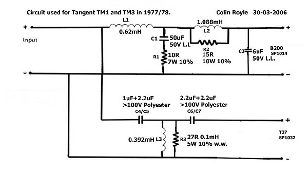
The KEF 104aB crossover with shorted terminal
IRL

And measured with Woofer Tester 3

The woofer section and the KEF B200 SP104 (that has an inductance of 0.42mH while the croosover was designed for SP 1039 with 0.25 mH inductance). Looks like a low pass filter at 2-3 kHz and then some amplitude adjustements 600-1200 Hz. The good news is that the two coils in series with the woofer only brings up system Q marginally from 0.95 to 1.05 so it appears that the previously tested range of caps 400-800 µF should cover what I will need in the final design.

Then the tweeter crossover, it looks different than some SPICE models I have seen
http://www.diyaudio.com/forums/multi-way/189530-kef-104-kef-104ab-mkii-spice.html
I measured all the components and they all match including the resistance of the coil, the main difference is that I use only plastic film caps not electrolytic and my filters are held together by screws and alligator clips

Looking at the curves it is not obvious how this will help lifting response above 10 kHz and reduce the hump at 10 kHz.
I have to measure with and without the filter to see how it works.
As I do not use the original driver I expect to fiddle with the crossover to get the two drivers to match up
IRL
And measured with Woofer Tester 3
The woofer section and the KEF B200 SP104 (that has an inductance of 0.42mH while the croosover was designed for SP 1039 with 0.25 mH inductance). Looks like a low pass filter at 2-3 kHz and then some amplitude adjustements 600-1200 Hz. The good news is that the two coils in series with the woofer only brings up system Q marginally from 0.95 to 1.05 so it appears that the previously tested range of caps 400-800 µF should cover what I will need in the final design.
Then the tweeter crossover, it looks different than some SPICE models I have seen
http://www.diyaudio.com/forums/multi-way/189530-kef-104-kef-104ab-mkii-spice.html
I measured all the components and they all match including the resistance of the coil, the main difference is that I use only plastic film caps not electrolytic and my filters are held together by screws and alligator clips
Looking at the curves it is not obvious how this will help lifting response above 10 kHz and reduce the hump at 10 kHz.
I have to measure with and without the filter to see how it works.
As I do not use the original driver I expect to fiddle with the crossover to get the two drivers to match up
This is how the 104aB mates with the T27 and SP1014
The 2-3 kHz dip gets far with reverse phase tweeter
The dip at 6-7 kHz is due to not flush mounting the tweeter.
The tweeter lack of output above 12 kHz ( or to much in the 4-12 kHz range) persist and removing the RC links does nothing to change this.

I tried reducing the 2.6mH coil to 1.2 mH to try to fill out the 2-3 kHz gap
Black curve. It worked but I also got a nasty peak at 2 kHz.
Adding a Zobel improved it a lot but it still was a bit to hot 1-2 kHz.

I tried a 1.8 mH coil and it really did not get better, I am also less than impressed with the T27. This is compounded by the fact that a 20mm dome will strain to reach down to a 200mm driver.
So the new game plan is to use an other vintage dome the Seas H087. This is 1.5" dome to the tweeter will have larger diameter voice coil than the woofer!
This will be crossed over all the way down at 2 kHz using a 24 dB/octave LR filter. I expect to top off the high range with small super tweeter using a 12 dB high pass filter in the 8-10 kHz range. I have a ribbon, some 1/2" domes and even some cone tweeter that might do the trick
The 2-3 kHz dip gets far with reverse phase tweeter
The dip at 6-7 kHz is due to not flush mounting the tweeter.
The tweeter lack of output above 12 kHz ( or to much in the 4-12 kHz range) persist and removing the RC links does nothing to change this.
I tried reducing the 2.6mH coil to 1.2 mH to try to fill out the 2-3 kHz gap
Black curve. It worked but I also got a nasty peak at 2 kHz.
Adding a Zobel improved it a lot but it still was a bit to hot 1-2 kHz.
I tried a 1.8 mH coil and it really did not get better, I am also less than impressed with the T27. This is compounded by the fact that a 20mm dome will strain to reach down to a 200mm driver.
So the new game plan is to use an other vintage dome the Seas H087. This is 1.5" dome to the tweeter will have larger diameter voice coil than the woofer!
This will be crossed over all the way down at 2 kHz using a 24 dB/octave LR filter. I expect to top off the high range with small super tweeter using a 12 dB high pass filter in the 8-10 kHz range. I have a ribbon, some 1/2" domes and even some cone tweeter that might do the trick
It's interesting that a big bass coil cured most of the 2kHz peakiness of the bextrene unit. This is the thing we all fear with those old drive units. 🙂
Have you found a formula for the series resistance with the tweeter coil to match the Q of the tweeter?
So far I haven't paid attention to this, but can hear a little ringing from the circuit. I'm guessing 1 ohm might fix it with my Morel 900Hz jobbie.
My latest project with a Morel CAT 298 soft dome and a typical low voicecoil inductance (1mH?) 8" paper bass:
I also need to add (guesses) 2.2R in series with the tweeter to roll it off a bit at the top. Just like KEF! 🙂
Have you found a formula for the series resistance with the tweeter coil to match the Q of the tweeter?
So far I haven't paid attention to this, but can hear a little ringing from the circuit. I'm guessing 1 ohm might fix it with my Morel 900Hz jobbie.
My latest project with a Morel CAT 298 soft dome and a typical low voicecoil inductance (1mH?) 8" paper bass:
An externally hosted image should be here but it was not working when we last tested it.
An externally hosted image should be here but it was not working when we last tested it.
An externally hosted image should be here but it was not working when we last tested it.
An externally hosted image should be here but it was not working when we last tested it.
An externally hosted image should be here but it was not working when we last tested it.
I also need to add (guesses) 2.2R in series with the tweeter to roll it off a bit at the top. Just like KEF! 🙂
I have scrapped this project, I had glued the bitumenboard with latex glue (seam sealer) and when dropping the box a panel came loose. Next time use proper silicone glue). But that damping I have learned will be used in other projects. Horns, Open baffles, quarter wave pipes...
Hi,
Had a similar problem years ago using the "special" adhesive
for bitumen pads. In hindsight good contact adhesive I reckon.
rgds, sreten.
Had a similar problem years ago using the "special" adhesive
for bitumen pads. In hindsight good contact adhesive I reckon.
rgds, sreten.
The problem I face is finding a low emission adhesive that when used in a sealed box speaker to fix bitumen pads to the internal walls of a birch play cabinet, will emit minimal vapour fumes inside the box which could affect driver parts / surrounds etc.
Last edited:
- Status
- Not open for further replies.
- Home
- Loudspeakers
- Multi-Way
- One BC, homage to a classic vintage design