Hello friends, once again, here we go.
Yes, I used the search function, but the answers were fragmented and ambiguous.
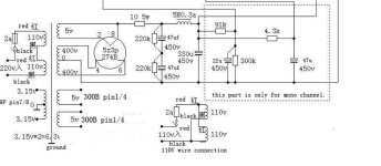
I would like to improve my CLC PSU for this 300b set amp, which with some modifications is really really better.
I see that many builders implement PIO or film caps in the PSU, many others shunt electrolytics with films (which is quite debated), my question would be, in which position, and with what values should here PIOs or film caps go in?
I see the first reservoir cap before the choke would be a nice place, with around 30uF.
Now rectifier tube is a 83, mercury vapor.
Then what else?
Being the last cap in the AC signal path, should I add one PP or PIO cap paralleling that 330uF?
I see the reasons why, the different impedance response of electrolytics at different frequencies (and I understand that small film caps shunting bigger EL work in the range oh MHz), but what are your ideas/opinions on that?
Or having a full film PSU through Wima DC link? A valid and costly alternative?
Why many spend big money on that stolen caps?
Will it be something audible or just self-persuasion?
There are so many cooks in this kitchen, I'm quite baffled.
Thank you to those who will give their 2 cents.
Yes, I used the search function, but the answers were fragmented and ambiguous.
I would like to improve my CLC PSU for this 300b set amp, which with some modifications is really really better.
I see that many builders implement PIO or film caps in the PSU, many others shunt electrolytics with films (which is quite debated), my question would be, in which position, and with what values should here PIOs or film caps go in?
I see the first reservoir cap before the choke would be a nice place, with around 30uF.
Now rectifier tube is a 83, mercury vapor.
Then what else?
Being the last cap in the AC signal path, should I add one PP or PIO cap paralleling that 330uF?
I see the reasons why, the different impedance response of electrolytics at different frequencies (and I understand that small film caps shunting bigger EL work in the range oh MHz), but what are your ideas/opinions on that?
Or having a full film PSU through Wima DC link? A valid and costly alternative?
Why many spend big money on that stolen caps?
Will it be something audible or just self-persuasion?
There are so many cooks in this kitchen, I'm quite baffled.
Thank you to those who will give their 2 cents.
Attachments
This is the problem. In the end you have to try it for yourself to see if it is worth it.There are so many cooks in this kitchen, I'm quite baffled.
I mainly don't use pio because of size, price and how to put in or on my chassis.
The DC links are in my eyes the biggest value in audio. Typically I uses 40-75uF and they can be had 2nd hand on this forum or I buy them from mouser. And 10euro is not that bad for an excellent pp cap.
So just start somewhere. Replace the first cap with pio and see if you can notice. Then replace the last 330uF with a polyprop of say 40-100. And see if it matters to you in your system.
Last edited:

I wouldn't use old stock PIO personally, they colour the sound too much. I use modern production motor run caps and DC link caps.
330 µF is a big value though, I wonder if it's truly needed. You could try PSUD to determine if a smaller value would be acceptable.
330 µF is a big value though, I wonder if it's truly needed. You could try PSUD to determine if a smaller value would be acceptable.
The modern cheap plastic motor runs sound very average - nothing like DC Links. The KBG PIOs are specially good - I've auditioned all these choices as cathode bypass caps where you can hear differences better. Mind, the biggest KBG I have is 6uF at 600V - they are huge, but also good as coupling caps. Look up some of the reviews of these caps.
Last edited:
Although they come in 2/4/6 uF version, a first PSU cap before the choke needs 20/40uF... I know they're great, I use them on other placesTry DC Link capacitors first, like Kemet and Vishay. If you want big and very good get the Russian KBG PIO caps. But they are BIG. I got some from Bulgaria, and you find them in the old Soviet bloc countries.
Is there a reason to put a say, 2uF film cap after the last EL in the PSU? So that the AC coming back catches plastic instead of aluminum?
If yes, why?
If yes, why?
Why use old tech PIO caps at all?
Why in a power supply?
What sound improvement are they supposed to provide?
Why in a power supply?
What sound improvement are they supposed to provide?
If you're after the sound of PIOs, hunt down some Bosch MPs (can be found in some washing machines or AC), also Siemens MKVs.
Good question.Why use old tech PIO caps at all?
Why in a power supply?
What sound improvement are they supposed to provide?
I know we are going into an endless discussion. But since you asked this is my response:
Virtually all capacitors with the most positive subjective qualities have paper or paper/oil as dielectric :
https://www.humblehomemadehifi.com/download/Humble Homemade Hifi_Cap-Test-Ratings.pdf
This is just one person's judgement. So this is not proof of anything. At least among many single ended tube amp builders there are many who vouch for the "sound of pio" in a psu.
Objectively they have lower ESR than lytics and can withstand very high voltages and last longer than lytics.
And of course Polypropylen caps can handle more ripple than electrolytic.
In my most recent builds I've used all film caps in the power supply, DC Links by Panasonic and Kemet, and in the past I used motor run caps, which are polypropylene in oil, in a PP 6B4G build.
I can't say that I did any A-B listening vs electrolytics though. My overall impression is that they are faster and cleaner but perhaps it's just my imagination. I don't think I've ever used paper in oil in a PS but I've used them occasionally as coupling caps.
Putting any possible sonic benefits aside, I figure DC Links will be more reliable long term since they're not as sensitive to heat. For electrolytics I always recommend using ones rated at 105° and 10,000 hours. The films have lower ESR and are relatively inexpensive so, if you have the space I would suggest using them in place of an electrolytic rather than using them in parallel with an electrolytic.
If I had to use them in combination with electrolytics I'd probably use them later in the PS rather than as the first cap, so the cap from which B+ is taken and whatever supplies the inputs, but I'm not sure if there's any technical basis for that.
As an aside . . . I've seen that cap comparison referenced on many occasions and, as Bas points out, it is just one person's opinion. There's more to it than that though . . . The link only shows the comparison chart but if you read the whole test you will see that the website is all about speakers and has nothing to do with amps at all.
The tests were done in a variety of speakers with, presumably, totally different crossover circuits. The author clearly says, "The subjective results of this test are meant to give you a general idea of the audible differences between capacitors when used in passive loudspeaker crossovers."
Despite this, many people seem to consider it as gospel and seem to think that his impressions can be applied universally. Every time I've seen it referenced it has been in discussions of caps used in amplifiers, most often in discussions of coupling caps and here in a discussion of power supply caps.
When caps perform different functions and (in the case of coupling caps) require much different capacitance values I'm a bit skeptical. It may have some limited value when applied to amplifiers but I certainly wouldn't consider it to be definitive or universally valid, even putting aside that it's subjective.
Second your opinion. Many different brands of modern motor run capacitors use vegetable oil as filler. Vegetable oil has high dielectric constant, which allows putting more microfarads in smaller size. It is also environment-friendly. But these capacitors sound terrible - I know first hand by using them in speaker crossovers. An exception is GE capacitors filled with Dielectrol - proprietary hydrocarbons that can be considered improved version of mineral oil.The modern cheap plastic motor runs sound very average - nothing like DC Links. The KBG PIOs are specially good - I've auditioned all these choices as cathode bypass caps where you can hear differences better. Mind, the biggest KBG I have is 6uF at 600V - they are huge, but also good as coupling caps. Look up some of the reviews of these caps.
KBG capacitors are so god because they have foil electrodes. Most capacitors of today use metallization electrodes. Metallization, unlike solid metal, has specific kind of voltage-dependent distortion called flicker. For the same reason bulk foil resistors are superior to metallized film resistors.
I have an explanation and developed a theory on capacitor, cable and the audibility of many things considered as snake oil, buy I need more free time and finances to shape it into objective measurements. It has nothing to do with the transfer of electrical signals, but acoustic properties of materials, which reflect on the acoustic output on the speakers.
Hint: Oil acts as dampener
Hint: Oil acts as dampener
Can't see the advantage over impressive quality of commercial modern capacitors made by the big players in the field, available from large serious suppliers such as Mouser, Digikey, Farnell.
Why go backwards 70 years in technology?
I started building amplifiers in 1969 and even back then paper in oil meant musty old cheesy components Electronics shops put in the bargain bins to get rid of them faster.
Even here in Argentina we had 2 top notch plants: Mallory and Philips making best quality "plastic" caps, plus Brazilian made Siemens and ubiquitous Japanese "green" caps.
In my most recent builds I've used all film caps in the power supply, DC Links by Panasonic and Kemet, and in the past I used motor run caps, which are polypropylene in oil, in a PP 6B4G build.
I can't say that I did any A-B listening vs electrolytics though. My overall impression is that they are faster and cleaner but perhaps it's just my imagination. I don't think I've ever used paper in oil in a PS but I've used them occasionally as coupling caps.
Thank you for your thorough answer, would youimd putting a couple schematics, just B+, of your builds?
Sure, here are the PS schematics. Nothing too unusual in terms of the caps themselves, just using DC Links instead of electrolytics. The power supplies are a bit different than most, though.Thank you for your thorough answer, would youimd putting a couple schematics, just B+, of your builds?
The Nuance uses a split supply, part tube rectified, part SS. The tube section uses a 5AR4 to provide slow startup to the outputs. The SS part supplies the inputs. It was necessary because I used a voltage regulator tube to supply the inputs and I needed it to start up quickly. Startup was inconsistent when it was supplied by the 5AR4. I did use electrolytics in the heater supply to the 26s but the rest are all DC Links.
The power supply for the Cockeyed Monkey is also a bit unusual. It's a "cockeyed bridge" which is essentially SS but it uses an inexpensive 6AX4GTB damper diode to provide a slow start.
Here are links to the build threads if you're interested in more info:
https://www.audiokarma.org/forums/index.php?threads/the-nuance-my-inverted-set-diy-project.990205/
https://www.audiokarma.org/forums/i...ckeyed-monkey-a-directly-coupled-set.1040847/
Metallization, which is produced by metal vapor deposition, results in a layer of metal particles loosely connected to each other. An analogy is a layer of sand. Metal-to-metal contact conduction is voltage-dependent: the conductivity may be lost at certain low voltage. This is a well-known effect in capacitors whose electrodes are not welded to outlet wires; such capacitors require a minimum biasing voltage for proper operation. In a metallized film capacitor, voltage increase causes recruitment of increased number of metal particles to the conductive layer, and voltage decrease causes particle exclusion. This is called flicker effect.
- Home
- Amplifiers
- Tubes / Valves
- Once again, PIO caps in tube PSU (SET)