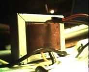
I have a couple of OPT's from an old Sony reel to reel that drove 6AQ5's in SE config. They have the standard 8r secondaries, but also 600r windings that drove a line out (presumably).
Anyway, they look like good quality trannys, so I was considering a pair of SE monoblocs for listening at my computer, but didn't know if I could make use of the 600r taps. I perhaps cathode feedback?
Anyway, they look like good quality trannys, so I was considering a pair of SE monoblocs for listening at my computer, but didn't know if I could make use of the 600r taps. I perhaps cathode feedback?
Attachments
I'm on the watch for something similar to pop up again on E-bay. Snoozed through the last one. The experiment will be to try the extra secondary winding - 
 - in series with the output tube grid.
- in series with the output tube grid.Hi !
Assuming primary is 6K, Z ratio would be 10 and turns ratio 3.16.
Says 30%. Good for use in Ultra Linear configuration.
Yves.
Assuming primary is 6K, Z ratio would be 10 and turns ratio 3.16.
Says 30%. Good for use in Ultra Linear configuration.
Yves.
rdf said:I'm on the watch for something similar to pop up again on E-bay. Snoozed through the last one. The experiment will be to try the extra secondary winding -
Huh?! What kind of evil plan are you scheming there?
Evil or daft  , you decide after reading my reasoning.
Feedback's effectiveness partially depends on the linearity of the return path. The best way for me to visualize this is with an extreme or limiting example. Imagine the general case of returning the feedback to the inverting node through a diode. The gain will be reduced but the feedback circuit will also generate new distortion on the output. Returning to reality, I think it's correct to say all feedback loops do this to some extent because no matter where you return the correction it's never in a perfectly linear relationship to the output. In the case of cathode feedback the cathode to plate transfer function is slightly different than that from grid to plate so the 'correction' won't perfectly follow theory. On balance it still reduces distortion on the output but at the expense of that well known mechanism whereby low order harmonic components are supressed at the expense of generating lower levels of higher harmonics not originally present.
A separate secondary winding provides an opportunity to apply the corrective signal directly to the grid, the same terminal accepting the input signal. Use a 600 ohm grid stopper and strap the winding across it. If I understand the voltage phases correctly, doing so also applies an opposing voltage to that of the driver plate. This should mean the driver sees a higher impedance and though you wouldn't measure lower distortion interstage - because it's now the sum of driver signal and feedback signal - the driver should actually be operating more linearly. Finally, 600 ohms is nothing in a grid circuit. There should be plenty of latitude to adjust the feedback winding's termination to optimize the correction and flatten frequency response above the audio band.
One last thought, while it's true that the signal on the the 600 ohm winding won't be identical to that on the 8 ohm tap, that's a constant no matter where you tie it anyway. That 'feedback loop distortion' can't be corrected. And now you see why I want to try it with cheap trannies too. 😉
, you decide after reading my reasoning. Feedback's effectiveness partially depends on the linearity of the return path. The best way for me to visualize this is with an extreme or limiting example. Imagine the general case of returning the feedback to the inverting node through a diode. The gain will be reduced but the feedback circuit will also generate new distortion on the output. Returning to reality, I think it's correct to say all feedback loops do this to some extent because no matter where you return the correction it's never in a perfectly linear relationship to the output. In the case of cathode feedback the cathode to plate transfer function is slightly different than that from grid to plate so the 'correction' won't perfectly follow theory. On balance it still reduces distortion on the output but at the expense of that well known mechanism whereby low order harmonic components are supressed at the expense of generating lower levels of higher harmonics not originally present.
A separate secondary winding provides an opportunity to apply the corrective signal directly to the grid, the same terminal accepting the input signal. Use a 600 ohm grid stopper and strap the winding across it. If I understand the voltage phases correctly, doing so also applies an opposing voltage to that of the driver plate. This should mean the driver sees a higher impedance and though you wouldn't measure lower distortion interstage - because it's now the sum of driver signal and feedback signal - the driver should actually be operating more linearly. Finally, 600 ohms is nothing in a grid circuit. There should be plenty of latitude to adjust the feedback winding's termination to optimize the correction and flatten frequency response above the audio band.
One last thought, while it's true that the signal on the the 600 ohm winding won't be identical to that on the 8 ohm tap, that's a constant no matter where you tie it anyway. That 'feedback loop distortion' can't be corrected. And now you see why I want to try it with cheap trannies too. 😉

Hi,
Here is a picture of my 6aq5 se stereo amp using the same opt's as you have. I did not use the 600r windings, though I have thought about using them to drive a subwoofer. Currently, I am using this amp at the office with a MAC as the source.
Check out my web site if you want more details of this amp.
Regards,
Danny
Here is a link to a post by member Planet10 concerning these OPTs.
Planet10 Post
dg
Here is a picture of my 6aq5 se stereo amp using the same opt's as you have. I did not use the 600r windings, though I have thought about using them to drive a subwoofer. Currently, I am using this amp at the office with a MAC as the source.
An externally hosted image should be here but it was not working when we last tested it.
Check out my web site if you want more details of this amp.
Regards,
Danny
Here is a link to a post by member Planet10 concerning these OPTs.
Planet10 Post
dg
rdf said:Evil or daft
Feedback's effectiveness partially depends on the linearity of the return path. The best way for me to visualize this is with an extreme or limiting example. Imagine the general case of returning the feedback to the inverting node through a diode. The gain will be reduced but the feedback circuit will also generate new distortion on the output. Returning to reality, I think it's correct to say all feedback loops do this to some extent because no matter where you return the correction it's never in a perfectly linear relationship to the output. In the case of cathode feedback the cathode to plate transfer function is slightly different than that from grid to plate so the 'correction' won't perfectly follow theory. On balance it still reduces distortion on the output but at the expense of that well known mechanism whereby low order harmonic components are supressed at the expense of generating lower levels of higher harmonics not originally present.
A separate secondary winding provides an opportunity to apply the corrective signal directly to the grid, the same terminal accepting the input signal. Use a 600 ohm grid stopper and strap the winding across it. If I understand the voltage phases correctly, doing so also applies an opposing voltage to that of the driver plate. This should mean the driver sees a higher impedance and though you wouldn't measure lower distortion interstage - because it's now the sum of driver signal and feedback signal - the driver should actually be operating more linearly. Finally, 600 ohms is nothing in a grid circuit. There should be plenty of latitude to adjust the feedback winding's termination to optimize the correction and flatten frequency response above the audio band.
One last thought, while it's true that the signal on the the 600 ohm winding won't be identical to that on the 8 ohm tap, that's a constant no matter where you tie it anyway. That 'feedback loop distortion' can't be corrected. And now you see why I want to try it with cheap trannies too. 😉
Wow... you lost me three times in there, but i think I see what you are shooting for. I'd be very interested to read about the results.
Ciscokid said:Hi,
Here is a picture of my 6aq5 se stereo amp using the same opt's as you have. I did not use the 600r windings, though I have thought about using them to drive a subwoofer. Currently, I am using this amp at the office with a MAC as the source.
Check out my web site if you want more details of this amp.
Regards,
Danny
AMAZING! That is incredibly helpful. I hunted down the link to the auction for those trannys and there wer VERY detailed specs, and the diagrams on your site will be invaluable. I even have that same power transformer (the whole power board actually), but i have been too lazy trace out the circuit.
If i may ask you one more question... what is the purpose of the 12BH7 in the power supply?
I sure does beg to be tried as cathode feedback, doesn't it? The 340 ohm DCR of the 600 winding might turn out to be about right to bias a 6V6/6AQ5. Expect the DCR to drop a little as the copper wire warms up.
-- Dave
-- Dave
aletheian said:
If i may ask you one more question... what is the purpose of the 12BH7 in the power supply?
if memory serves me....maybe I even have original schematic for that RtR...12BH7 is in oscillator circuit......
I don't know the particular details of this RTR, but all tape recorders use a "bias oscillator" to apply a high frequency signal to the record and erase heads. This generates a background magnetic field that is a frequency too high for the tape to record. This "biases" the tape up into a linear region of its BH (magnetic) curve.
A 12BH7, 6CG7, or 6SN7 was common for this application.
A 12BH7, 6CG7, or 6SN7 was common for this application.
tubelab.com said:I don't know the particular details of this RTR, but all tape recorders use a "bias oscillator" to apply a high frequency signal to the record and erase heads. This generates a background magnetic field that is a frequency too high for the tape to record. This "biases" the tape up into a linear region of its BH (magnetic) curve.
A 12BH7, 6CG7, or 6SN7 was common for this application.
Yes, I see it in the schem. The 12bh7 is tied to the heads... so that is most likely correct.
(I am a little in the dark when it comes to tape recording apparatus...)
Hi aletheian,
Thanks for the kind comments.
I will have to defer to others on this i'm afraid. 😕 I only know some of the basics when it comes to this stuff. However, I can reverse engineer when pressed
Best regards,
Danny
Thanks for the kind comments.
aletheian said:.. what is the purpose of the 12BH7 in the power supply?
I will have to defer to others on this i'm afraid. 😕 I only know some of the basics when it comes to this stuff. However, I can reverse engineer when pressed
Best regards,
Danny
Yes... a tempting idea... a bit nerve-wrecking though as far as the drift.Dave Cigna said:I sure does beg to be tried as cathode feedback, doesn't it? The 340 ohm DCR of the 600 winding might turn out to be about right to bias a 6V6/6AQ5. Expect the DCR to drop a little as the copper wire warms up.
-- Dave
If that works, then the Zo would be nice and low (relatively speaking), so the damping factor would be better... probably still under 1 though.
aletheian said:Yes... a tempting idea... a bit nerve-wrecking though as far as the drift.
I wouldn't expect things to drift around too much once everything is warmed up. Just that the tube might be biased a little cold when you first turn everything on.
The relatively high DCR of the 600R winding reminds up that it was not intended to carry DC current, so I would keep the idle current fairly low...
If that works, then the Zo would be nice and low (relatively speaking), so the damping factor would be better... probably still under 1 though.
Certainly it might (hopefully should) make any other NFB unnecessary.
Personally, I think the entire issue of damping factor is over rated. No doubt it depends on the speakers you're driving. John Swenson is driving Lowthers with EL84's with no NFB whatsoever. I don't remember the details, but he must have an output Z of something in the neighborhood of 80 ohms into an 8 ohm load. That's a VERY low DF, but he seems to like the sound.
As a very broad generalization, it seems that efficient full range drivers seem happy - maybe even happier - with low DF. These are the drivers that people tend to use with SET's with zero NFB.
Anyway, if the OT's were sitting on MY bench, I would have to try them with the 600R winding in the cathode. There's no way anyone could talk me out of trying it. 🙂
-- Dave
Dave Cigna said:
Anyway, if the OT's were sitting on MY bench, I would have to try them with the 600R winding in the cathode. There's no way anyone could talk me out of trying it. 🙂
-- Dave
Ok. Doin' it. I have a pair of single driver transmission line speakers in the pipe as a next project... maybe I'll combine the two into one effort.
how about something like this...
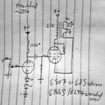
I looked around to see what parts I had and then brainstormed a bit and came up with this: 6SN7 choke-loaded driver with LED bias feeding a triode strapped EL84? Nice and simple and good for around 2 watts... enough for listening volume at my computer.
280v or so B+ should put somewhere around 260v on the plates of both the driver and the output tube. Choke loading the 6SN7 should give it enough gain to drive the trioded EL84 even with the cathode feedback, and the 300-ish DCR of the 600r secondary tap should be somewhere in the vicinity of biasing the tube up right with a 2.5K load I think (i just sketched the design... I'll plot the load lines later).
What do you think?
Attachments
Dave Cigna said:Expect the DCR to drop a little as the copper wire warms up.
-- Dave
umm not to barge in here, but doesn't the resistance of a metal increase when it heats up?
sorenj07 said:umm not to barge in here, but doesn't the resistance of a metal increase when it heats up?
Yeah, you're right.
 My mistake. I know that the change can be significant with copper as opposed to store-bought resistors. My poor memory got it backwards.
Thanks.
Dave Cigna said:
Yeah, you're right.
Thanks.
Hmmm... do you think "signifigant" as in + 10%, or 'signifigant' as in+30% or more?
- Status
- Not open for further replies.
- Home
- Amplifiers
- Tubes / Valves
- Old Sony SE OPT's /w 600r tap... cathode feedback maybe?