So I was messing with current sources for unrelated reasons and had a bit of a thought...
You know how mosfets have this annoyingly low and inconstant transconductance? You know how you can build a current source by wrapping an opamp around a mosfet and sense resistor?
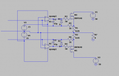
It occurred to me that by floating the opamp supplies on the output node, one could remove the supply voltage limit and that the local feedback would replace a rather variable transconductance with one having a defined value, and (providing the drive keeps both current sources at least slightly conducting) would remove the need to match mosfets in a multiple device output stage.

As drawn, the two control inputs are virtual grounds referenced to the output node, so it is current in/current out, the adaption to voltage input is obvious but then requires the driver to also be able to get outside the rails to drive the fets hard on.
Further, making those opamp supplies bootstrapped from the output would allow the gates to swing outside the supply rails without needing an extra supply, allowing the mos to get hard on even close to the rails, a couple of largish caps, some zenners and a pair of current sources or resistors at a minimum I would think, but less messy then a separate controls supply.
One possible downside is that the point where one device cuts off will tend to be quite a hard transition unless something is done to prevent this in the driver stage (got some ideas).
Am I nuts, or is this a sane notion? Power amps are not my usual stomping ground, and hybrids with opamps as well as transistors less so (I have never really understood why that is not a more common topology, modern opamps are quick enough to not screw up the stability margins in this sort of thing).
Regards, Dan.
You know how mosfets have this annoyingly low and inconstant transconductance? You know how you can build a current source by wrapping an opamp around a mosfet and sense resistor?
It occurred to me that by floating the opamp supplies on the output node, one could remove the supply voltage limit and that the local feedback would replace a rather variable transconductance with one having a defined value, and (providing the drive keeps both current sources at least slightly conducting) would remove the need to match mosfets in a multiple device output stage.
As drawn, the two control inputs are virtual grounds referenced to the output node, so it is current in/current out, the adaption to voltage input is obvious but then requires the driver to also be able to get outside the rails to drive the fets hard on.
Further, making those opamp supplies bootstrapped from the output would allow the gates to swing outside the supply rails without needing an extra supply, allowing the mos to get hard on even close to the rails, a couple of largish caps, some zenners and a pair of current sources or resistors at a minimum I would think, but less messy then a separate controls supply.
One possible downside is that the point where one device cuts off will tend to be quite a hard transition unless something is done to prevent this in the driver stage (got some ideas).
Am I nuts, or is this a sane notion? Power amps are not my usual stomping ground, and hybrids with opamps as well as transistors less so (I have never really understood why that is not a more common topology, modern opamps are quick enough to not screw up the stability margins in this sort of thing).
Regards, Dan.
Attachments
Last edited:
Making v3 and v4 might be tricky and I cant see how these will goe past the rails. But still an interesting idea. Did you run the sim?
Need to design an input stage and overall feedback before I can run it, also find a suitably quick opamp, be a shame for the opamp here to wind up limiting overall loop gain at high frequency.
As for V3 and 4, largish electrolytic to the output rail, zenner voltage clamp and resistor or current source from each supply rail?
As the output voltage swings up it will take the cap with it, and as long as the time constant is long compared to an audio cycle the cap will hold the opamp supply in a working region long enough for the cycle to complete, and can actually put the opamp supply outside the fet main supply (Think the boost cap in a buck regulator, kind of, sort of).
Needs a whole load of diodes and **** scattering around to make it well behaved in overload and to ensure nothing too awful happens during startup, but I think the huge amount of local feedback should linearise the output stage quite nicely.
My real intention was to come up with something to make paralleling modern mosfets less painful (I despise designs needing matched pairs or quads), which this (with just a little bias) should do as it essentially takes the question of threshold voltage and power device transconductance out of the picture.
We will see what spice has to say once I have an input section and feedback doings drawn up, what I was hoping for was for someone to point out the showstopper.
I tried simming a class A version of almost exactly that cct concept quite some time ago. The simulator I used, Simetrix, wouldn't allow the opamp supply rails to be referenced to a moving node. But, yeah, I think it's an idea worth following. One thing is the opamp only has to swing the error voltage, not the entire signal. Makes life a lot easier for it. Quiescent current should be rock steady too. I'll watch this thread.Did you run the sim?
Very interested to see where this leads.
One question - by bootstrapping the opamp supply from the output do we lose the reduction of the Cgs brought by the source follower config? Just wondering which opamps are comfortable driving capacitive loads of 1-10nF?
One question - by bootstrapping the opamp supply from the output do we lose the reduction of the Cgs brought by the source follower config? Just wondering which opamps are comfortable driving capacitive loads of 1-10nF?
I believe the Vellement K4020 amplifier kit used this approach
https://www.velleman.eu/downloads/0/manual_k4020.pdf
https://www.velleman.eu/downloads/0/manual_k4020.pdf
So I was messing with current sources for unrelated reasons and had a bit of a thought...
You know how mosfets have this annoyingly low and inconstant transconductance? You know how you can build a current source by wrapping an opamp around a mosfet and sense resistor?
It occurred to me that by floating the opamp supplies on the output node, one could remove the supply voltage limit and that the local feedback would replace a rather variable transconductance with one having a defined value, and (providing the drive keeps both current sources at least slightly conducting) would remove the need to match mosfets in a multiple device output stage.
As drawn, the two control inputs are virtual grounds referenced to the output node, so it is current in/current out, the adaption to voltage input is obvious but then requires the driver to also be able to get outside the rails to drive the fets hard on.
Further, making those opamp supplies bootstrapped from the output would allow the gates to swing outside the supply rails without needing an extra supply, allowing the mos to get hard on even close to the rails, a couple of largish caps, some zenners and a pair of current sources or resistors at a minimum I would think, but less messy then a separate controls supply.
One possible downside is that the point where one device cuts off will tend to be quite a hard transition unless something is done to prevent this in the driver stage (got some ideas).
Am I nuts, or is this a sane notion? Power amps are not my usual stomping ground, and hybrids with opamps as well as transistors less so (I have never really understood why that is not a more common topology, modern opamps are quick enough to not screw up the stability margins in this sort of thing).
Regards, Dan.
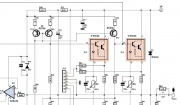
There's nothing wrong with the idea, it is the basic voltage controlled current source. The need for floating +/-15V supplies is a disadvantage but easily solved: supply the opamps through a pair of resistors & zener from the main supply, and bootstrap the resistor midpoint from Vout.
Edit: I see abrax mentioned the bootstrapping too. The cap load is much lower than the value of the cap because it will be in series with a highish resistor. I have used it in my paX amp with very high values, see C11, R36, R37, D10, in the attached, with no issue.
This gives you +/-15 floating on the output voltage.
Jan
Attachments
Last edited:
I believe the Vellement K4020 amplifier kit used this approach
https://www.velleman.eu/downloads/0/manual_k4020.pdf
I think the PFETs T10/11 are wrong drawn, Source and drain should be exchanged.
Attachments

Seems likely. Note that the Vellman design runs the current sources referenced against the rails not the output, but yea basically the same idea.
The cascoded 061 as an input stage is a nicely weird touch, especially love the way the feedback is organised!
Not too sure about 071s as mosfet drivers, I would have thought something with a rather beefier output current capability would be better.
You could take the Velmann variant and diddle it just a little by putting the load in the ground return to the power supply, and floating the caps, rectifier and transformer, upside would be that there would be no need for insulating washers on the power devices (Effectively ground the output node, seen that somewhere? Carver??).
As to the capacitive loading that is what the little clutch of passives is about, the gate resistor isolates the opamp output and the little cap shifts the feedback to before the big mosfet at high frequencies, we will see.
Many spice opamps have a nasty tendency to use node 0 rather then treating the opamp as a 5 terminal device, apparently when I asked TI about it for reasons of convergence in some spice implementations, but it does make this sort of thing harder then it needs to be to simulate with proper device models.
Last edited:
- Home
- Amplifiers
- Solid State
- Nuts things to do with opamps?