Working on the audio portion of my new amateur radio transmitter, it's basically a 70W class AB1 audio amplifier so I figure I'll let the audio guys have a look and see what improvements I can make. Radio guys are generally very securely in the "that's good enough" range of audio, but many times it just isn't and causes problems later.
That said-this is not a hi-fi design! Once the basic concept is established as not immediately going to melt into slag (the circuit presented here does not and actually works OK at the 45 watt power levels I've tested at) I need to limit the frequency response. I don't have a big enough 10K ohm resistor to properly load the secondary winding beyond 45W for more than a few seconds at a time.

Now, even though the desired frequency response is 100hz-10Khz, I've made little attempt at limiting the bandwidth so far. I am very open to suggestions on:
How to limit the bandwith, restricting it to 100hz-10Khz range
How to best apply some negative feedback around the whole amplifier. I've never been particularly good at making this decision.
Now, for the details:
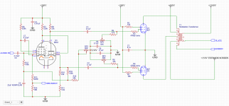
The 807's are running 600V anode and 300V on the screens, and -32v fixed bias on the grids. They can provide a maximum of 72W of power to the modulation transformer primary, and operate in class AB1...lots of class B but still AB1. Plate dissipation is not being violated at the idle conditions, and short of a key-down single tone test for tens of minutes (not realistic) they'll be fine.
The modulation transformer will provide between 8.4K to 9.1K plate-to-plate load for the 807's. It was actually designed for a military transmitter that used 807's as the modulator tubes. The operating point was taken from the original schematic and backed off a bit.
The 6BL8 input circuit is a very nice low-distortion design modified from an RCA 50W audio amplifier but it was designed for a 25v output swing. I have not gone through and checked the distortion at the 32 volt output level nor made allowances for the increased drive needed.
The modulation transformer is as follows:
807's drive a 8.4K centertapped primary winding
The secondary winding is a 10K winding designed to carry 130mA of standing RF current.
The tertiary winding is a 1000 ohm centertapped winding that provides modulated screen supply voltage from the centertap to one leg, for the RF final. The other half of this winding could be used as a negative feedback source, but it will be biased at +250 to 300v, with a voltage swing of 206 volts peak-to-peak.
Thanks any suggestions!
That said-this is not a hi-fi design! Once the basic concept is established as not immediately going to melt into slag (the circuit presented here does not and actually works OK at the 45 watt power levels I've tested at) I need to limit the frequency response. I don't have a big enough 10K ohm resistor to properly load the secondary winding beyond 45W for more than a few seconds at a time.
Now, even though the desired frequency response is 100hz-10Khz, I've made little attempt at limiting the bandwidth so far. I am very open to suggestions on:
How to limit the bandwith, restricting it to 100hz-10Khz range
How to best apply some negative feedback around the whole amplifier. I've never been particularly good at making this decision.
Now, for the details:
The 807's are running 600V anode and 300V on the screens, and -32v fixed bias on the grids. They can provide a maximum of 72W of power to the modulation transformer primary, and operate in class AB1...lots of class B but still AB1. Plate dissipation is not being violated at the idle conditions, and short of a key-down single tone test for tens of minutes (not realistic) they'll be fine.
The modulation transformer will provide between 8.4K to 9.1K plate-to-plate load for the 807's. It was actually designed for a military transmitter that used 807's as the modulator tubes. The operating point was taken from the original schematic and backed off a bit.
The 6BL8 input circuit is a very nice low-distortion design modified from an RCA 50W audio amplifier but it was designed for a 25v output swing. I have not gone through and checked the distortion at the 32 volt output level nor made allowances for the increased drive needed.
The modulation transformer is as follows:
807's drive a 8.4K centertapped primary winding
The secondary winding is a 10K winding designed to carry 130mA of standing RF current.
The tertiary winding is a 1000 ohm centertapped winding that provides modulated screen supply voltage from the centertap to one leg, for the RF final. The other half of this winding could be used as a negative feedback source, but it will be biased at +250 to 300v, with a voltage swing of 206 volts peak-to-peak.
Thanks any suggestions!
Last edited:
Nice amplifier.
Good adjustable fixed bias circuit values. Meets the 100k limit for g1.
Caution: RP1 and RP2, if either pot wiper opens up, be prepared for some smoke somewhere.
807, Output transformer, Power Supply.
Good adjustable fixed bias circuit values. Meets the 100k limit for g1.
Caution: RP1 and RP2, if either pot wiper opens up, be prepared for some smoke somewhere.
807, Output transformer, Power Supply.
Last edited:
Yeah. a pair of 1 ohm resistors in the cathodes of the 807's would go a long way towards implementing an overcurrent shutdown relay. Maybe better to put the 1 ohm resistor in the B+ lead and measure total plate current, instead. One less resistor, and more reliable shutdown of the plate voltage.
There's definitely going to be a few protection relays in the RF stages anyway, no reason at all to not put them on the modulator side too. Setting the plate voltage relay to trip and open up at 350mA would work, if this draws that much current it's definitely in a fault condition.
There's definitely going to be a few protection relays in the RF stages anyway, no reason at all to not put them on the modulator side too. Setting the plate voltage relay to trip and open up at 350mA would work, if this draws that much current it's definitely in a fault condition.
Last edited:
A single 4-65A.
1300V plate
250V screen
130mA plate current
Will take 2.5W of drive and put out around 130W of carrier.
1300V plate
250V screen
130mA plate current
Will take 2.5W of drive and put out around 130W of carrier.
Switch,
If a 1 Ohm resistor in the 807 plate lead cooks and opens, guess what happens . . .
The Screen Literally Cooks!
Ouch!
If a 1 Ohm resistor in the 807 plate lead cooks and opens, guess what happens . . .
The Screen Literally Cooks!
Ouch!
How to limit the bandwith, restricting it to 100hz-10Khz range
10 KHz of audio frequency response in an AM transmitter would make for a rather wide RF channel which may not even be legal on the ham bands.
Most AM phone transmitters are limited to about 3KHz. In a modern rig this and maybe some companding is done in a DSP chip, but the older AM rigs used HF roll off scattered through the audio chain. Frequencies below 300 hZ are usually rolled off as well to avoid wasting RF and audio power on frequencies that do not add to the intelligibility of speech. The best source of knowledge on this subject would be old ARRL handbooks and possibly some of the AM phone user groups.
There are a few SSB guys running "high fidelity" voice with 5 to 6 KHz upper limits. They claim (so far successfully) that they are using no more bandwidth than an AM phone guy, thus not violating any FCC rules. Most of these guys are in the south and run big power on 75 / 80 meters.
There is no limit on AM transmission width as far as the FCC is concerned. No issues with legality. The rules are very clear, "Not wider than needed for communications and conditions" but there are no defined bandwidths for full-carrier AM.
I limit my voice bandwidth before I ever send the audio to the modulator, and have selectable passbands of 200-3200hz, 100-4500hz, and 70-6000hz. Depending on conditions, all work very well, but obviously you have to make sure you're not stepping on someone else's toes at the wider bandwidths. Transmitted bandwidth is double the voice passband, so that 70-6000Hz passband transmits about a 12.5Khz wide signal. That's plenty wide enough to sound like a sportscaster, when conditions allow. The 200-3200hz passband puts out a 6.5khz wide signal, which is still natural sounding and very clear-without taking up double the bandwidth needed.
The limits are mostly because the modulation transformer is rated at (and actually measures!) 100hz-15Khz +/-0.5dB at full rated power-and it really delivers. By making sure the modulator is as flat and well behave as possible over that range, I can do my audio shaping with modern filters and processing.
I was thinking coupling capacitors driving the 807's could be reduced in value to cut out some of the lows, but wasn't sure about cutting the highs. It really isn't that critical, except for making sure the negative feedback loop doesn't cause a big problem later.
I'm still concerned about how to apply the negative feedback here-I could grab it from the secondary of the transformer but both secondaries are DC biased well above ground-with appropriate audio bypass caps on the screen winding, I could use that and a voltage divider to get the feedback signal I need.
The other method involves picking off a modulated output signal, recovering the audio on it, and applying the detected audio as negative feedback to the modulator. This allows for a little distortion correction of the actual transmitted signal, which does double-duty in cleaning up the output signal.
The 1 ohm resistor will dissipate 500mW at half an amp B+. A 2 watt flameproof will live forever.
I limit my voice bandwidth before I ever send the audio to the modulator, and have selectable passbands of 200-3200hz, 100-4500hz, and 70-6000hz. Depending on conditions, all work very well, but obviously you have to make sure you're not stepping on someone else's toes at the wider bandwidths. Transmitted bandwidth is double the voice passband, so that 70-6000Hz passband transmits about a 12.5Khz wide signal. That's plenty wide enough to sound like a sportscaster, when conditions allow. The 200-3200hz passband puts out a 6.5khz wide signal, which is still natural sounding and very clear-without taking up double the bandwidth needed.
The limits are mostly because the modulation transformer is rated at (and actually measures!) 100hz-15Khz +/-0.5dB at full rated power-and it really delivers. By making sure the modulator is as flat and well behave as possible over that range, I can do my audio shaping with modern filters and processing.
I was thinking coupling capacitors driving the 807's could be reduced in value to cut out some of the lows, but wasn't sure about cutting the highs. It really isn't that critical, except for making sure the negative feedback loop doesn't cause a big problem later.
I'm still concerned about how to apply the negative feedback here-I could grab it from the secondary of the transformer but both secondaries are DC biased well above ground-with appropriate audio bypass caps on the screen winding, I could use that and a voltage divider to get the feedback signal I need.
The other method involves picking off a modulated output signal, recovering the audio on it, and applying the detected audio as negative feedback to the modulator. This allows for a little distortion correction of the actual transmitted signal, which does double-duty in cleaning up the output signal.
Switch,
If a 1 Ohm resistor in the 807 plate lead cooks and opens, guess what happens . . .
The Screen Literally Cooks!
Ouch!
The 1 ohm resistor will dissipate 500mW at half an amp B+. A 2 watt flameproof will live forever.
Last edited:
Switch,
You are right!
Of course, the 1 Ohm resistor will last forever.
As to hearing if there is someone else on a frequency that is contained inside the wider AM modulator bandwidth, at least you will be in the AM phone portions of the Band.
But you have reminded me of the Record that was set in 1959, in the CW portion of a Band.
A coordinated session using 2 Philco Surface Barrier transistors, one as oscillator, and the other as an output amplifier, had an input power of 100mW on 10 Meters.
The output (probably about 65mW) was applied to a Beam antenna.
The receive antenna at the far end was also a Beam antenna.
The trick, was to point both beam antennas the Long Way around the World.
The path was 13,000 miles.
Only 65mW out of the QRP transmitter, went More than 1/2 way around the world.
I think that record from 1959 may still stand.
Anybody got one to break that?
I am talking about terrestrial communications, not deep space communications.
At the very least, that was the 'Roger Bannister Equivalent' of the day.
Last edited:
... The trick, was to point both beam antennas the Long Way around the World. The path was 13,000 miles. Only 65mW out of the QRP transmitter, went More than 1/2 way around the world.
I think that record from 1959 may still stand. ....
The monster, legendary, solar cycle 19. Could be true.
There is no limit on AM transmission width as far as the FCC is concerned.
Emissions 10.2 kHz to 20 kHz removed from the carrier must be attenuated at least 25 dB below the unmodulated carrier level, emissions 20 kHz to 30 kHz removed from the carrier must be attenuated at least 35 dB below the unmodulated carrier level,
47 CFR SS 73.44 - AM transmission system emission limitations. | CFR | US Law | LII / Legal Information Institute
https://www.nrscstandards.org/standards-and-guidelines/documents/standards/nrsc-1-c.pdf
Emissions 10.2 kHz to 20 kHz removed from the carrier.....
I followed those links and they apply to "broadcast" radio spectrum. The rules for ham radio are somewhat looser.
I know that the emission regs on the ham bands have been tightened up since the days of running Globe Kings and even old AM radio station equipment. I also read that the ARRL had proposed new emission designators with bandwidth restrictions. I haven't run AM in 30+ years, so I haven't kept up with the rules.
Either way suitable filtering on the audio input before the AM modulator can be a good choice as long as the modulator itself is not a gross producer of THD. I have seen high end ham guys run compressors and graphic equalizers, often from an old radio station or recording studio in their audio chain.
I met a guy nearly 20 years ago who ran some studio stuff into a big solid state HiFi amp, which fed a big SE tube amp OPT run backwards for his modulation transformer. His RF PA ran a pair of 833A's. I think his RF power was in the 500+ watt range, but the transformer did not complain since he cut all LF below 300 Hz.
Ya, added those links because it wasn't 100% clear if this was an amateur ham or broadcast AM tx. I still manage AM sites so playing it safe. 🙂I have seen high end ham guys run compressors and graphic equalizers, often from an old radio station or recording studio in their audio chain.
Not just studio gear. Years ago I converted a few AM stations to FM. Local ham guys caught wind of it and were happy to take the lower power tube backup transmitters off my hands - 1 kw+, 6 foot high, 800+ pounds - for conversion to amateur use. Understanding spouses apparently.
There were lots of old RCA, Gates, and other 500 watt AM radio stations in the 50's and 60's that ran 4 X 833A's. Two for the RF PA, and two for the modulator. More than a few of them wound up on the 160 meter ham band.
Not just studio gear. Years ago I converted a few AM stations to FM.
Bit OT but . . . . . . Did you ever have occasion to look in on CJRT 's transmitter? I used to drive between the lakehead and the big smoke a lot and early on they had a sound that no other station on air at the time could match. I'd always switch the tuning just south of Sudbury hoping to pick them up as soon as they were in range - which varied quiet a lot each time I came and went. I'd never thought that radio could sound so good until I heard them for the first time and every trip kept them on the dial until out of range again.
I've always wondered what their setup was. One DJ made a comment about it being an old analog transmitter (I thought "Oh, he means tube.") and that was one of the things that got me interested in building. Then at some point (late 90's or early 2000's?) the sound changed - going flat or losing dimensional depth. (After that their programming also seemed to bite the dust) I always figured they must have updated to a new transmitter but was never sure. Do you know anything about them?
Yeah, I have a single 833A here that has a bad filament. Was given to me when I sold my good 833A to the radio station locally that still had one running as their backup transmitter.
Brand new, unused tube, but as soon as they lit it up the filament went and so they were in a hard spot.
Anyway, back to the modulator.
I've got a few things to adjust in the schematic now, like upping the grid leaks on the 807's to 82K and changing the grid stopper to just 100R resistors, and adding a plate stopper of 22 ohms. The screen grids each get their bypass cap right at the screen pin instead of sharing a single one.
As to the negative feedback loop.
Can I come off the lower-voltage secondary with a high impedance voltage divider to ground (maybe a 200K and 10K which will draw about 1mA) and then feed that voltage back through the normal series resistor/parallel capacitor feedback loop scheme?
If I understand the schematic correctly, the cathode voltage of the triode section of the 6BL8 is being used to form a voltage divider (R16, R15 and RP3) to bias the contol grid of the pentode section of the 6BL8. C5 makes sure that the ac (signal) from the cathode of the triode section does not reach the control grid of the pentode section.
But does this not influence what is happening at the cathode of the triode section? What is the benefit of this topology over a topology which uses B+ or ground to form the voltage divider?
But does this not influence what is happening at the cathode of the triode section? What is the benefit of this topology over a topology which uses B+ or ground to form the voltage divider?
- Home
- Amplifiers
- Tubes / Valves
- Not quite HiFi-Radio Transmitter Modulator.