Can anyone provide a link that explains how I can combine the secondary voltages to produce the maxium output voltage. The secondaries are 125V,100v,75v and 50v. It says 150ma which I believe implies 150ma for each secondary. The box also says output volts from condenser input filter using 5u4 tube. the secondary also has 5v at 3A. for the rectifer tube. Is it possible to connect together the secondaries to produce 300-350volts. If not connected in phase, will the voltages subtract? How is phase determined, trial and error?
Of course I have no idea of the size of the transformer, but I should think that the rating of 150mA applies to the secondary in total.
The best way to determine phase is to use an oscilloscope. Failing that (and what I have done recently) is to connect the secondaries and connect the output to a fast-acting meter. If the voltage drops then it's out of phase; left powered the transformer will get very hot indeed. Normally with such transformers there are taps for the various voltages and a single 0v terminal.
7N7
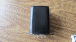
Thanks 7n7. Can't exactly follow your explanation. the transformer's dimensions are 4 in. H. X 3 1/4 W. X 3 in. wide and weighs 5 pounds. I have located the catalog but can not find the pin out. What is the 0v terminal for? Does the size and weight help determine what the current rating is for the transformer at 350volts. I do not have an oscilloscope yet. I would like to use this transformer for a push pull EL84 AMP. Any help from anyone is greatly appreciated. Yero
When 7n7 talks about connecting the secondaries and connect the output to a fast acting meter, do I connect the secondaries in series or parallel to obtain max. voltage at 150ma. does fast meter imply some thing like a fluke 87, I only have a 77- but can't an analog meter work good for this application. I can imidately recieve an indication of up or down in voltage using stand alone voltage meter with manual range voltage adjustment taps Analog meters, which I have access to. Is this what is ment by fast-acting meter? all assistance is appreciated. Yero
Can anyone provide a link that explains how I can combine the secondary voltages to produce the maxium output voltage. The secondaries are 125V,100v,75v and 50v. It says 150ma which I believe implies 150ma for each secondary. The box also says output volts from condenser input filter using 5u4 tube. the secondary also has 5v at 3A. for the rectifer tube. Is it possible to connect together the secondaries to produce 300-350volts. If not connected in phase, will the voltages subtract? How is phase determined, trial and error?
first you have to find out if the secondaries are separate windings or just a continuous winding with several taps...you need a dmm set to ohms to do this...the terminal marked 0 is usually the starting point to measure all other voltages...
Your meter will be fine and as Tony says it's a good idea to establish whether or not the secondaries are one continuous winding or separate ones, If this is the case of course you will have a 0v terminal and one each for 50v, 75v 100v and 125v. If the windings are separate, then there will be two terminals for each voltage.
7M7
7M7
looks like you have a bias trasformer with contunious windings .
http://www.bunkerofdoom.com/xfm/chicago1953/005.jpg
http://www.bunkerofdoom.com/xfm/chicago1953/005.jpg
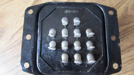
The transformer is 180-160-140-120-0 -120-140-160-180 and a 5 volt 3 amp tap yes they called it a bias transformer .Or a center taped 360,320,280,240 at 150 ma . What do you want to use it for ?
that would be the center tap of the 9 hv taps.7n7 there is no terminal for 0 volts
Battradio, If the transformer is a continous winding then there is a 0 volts or common winding? How do you determine the which terminal os the 0 volts
Well...
Start by measuring all the resistances - I suppose you keep one lead on terminal 1 and check in turn each of the others - I have never seen a transformer marked in this way, but the model number suggests 150mA as the absolute current - but it's hard to tell.
Nice -looking though isn't it?
7N7
Start by measuring all the resistances - I suppose you keep one lead on terminal 1 and check in turn each of the others - I have never seen a transformer marked in this way, but the model number suggests 150mA as the absolute current - but it's hard to tell.
Nice -looking though isn't it?
7N7
About 250 on the highest tap more of a 6cw5 power supply. Plus you need heater supply of 3 amps for 4 el84 and amp or two for the first stage and phase splitter stage . Edcor should have what you want off the shelf or they make it for you . As well as a number of other transformer companies. On my chicago trans the 1 ans 2 are the 120v the he hv ans lv last checking the taps with a meter like 7n7 said is a good start make sure the thing not shorted . Low reading are the norm some less than an ohm for some .triodethom, I was hoping to use the transformer for an el84 pp amp
terminals marked 1 ~ 12, nest thing to do is find out which numbers go together, the 110 volt winding will have lower dc resistance, the 5volt winding will have the lowest dc resistance, while the others will have higher dc resistance at the outermost tap than the other 2 windings...
this traffo will make a nice preamp PT......
this traffo will make a nice preamp PT......
Your best bet with that transformer is to trade it to someone that can use it for what it was intended . The B+ will only be about 212 volts ,plus you will need a 6.3 volt filament transformers . If you would use a full wave bridge you could get the proper B+ but wouldn't have enough current for two channels .
Mark
Mark
Battradio, If the bias transformer 1s rated at 150ma, is that not enough for a pp el84. What is a bias transformer intended for . bias means B+ right? I know that I would need 6.3 V for the filaments. Pin 1 and 2 read about 6 ohms which is AC IN. pin 12 and 13 are the five volts. pins 3+7=208v. pins 4+8, 5+9 and 6+10= 315v pin 11 + 3 read the most voltage at 416v and pin 11 + 6 read 343v. pin 11 and 7,8,9,10, read from200v down to pin 13+10 =24v. Another bit of info on the box it states Dc voltages used with reactor RC-12/150. must mean mobile 12v application. I believe I have seen transformers drive pp 6bq5 pp along with am/fm tube tuner with 150 ma. Does each pair put out 150ma or is the total taps collectively put out 150ma. I also believe the transformer is conservatively rated. Any assistance would be greatful. Yero
- Status
- Not open for further replies.
- Home
- Amplifiers
- Tubes / Valves
- NOS potted Chicago Transformer 1BC-150