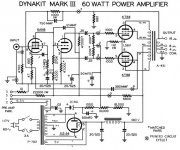
I ran across this Toshiba 6GB8 amplifier. 6GB8 is an esoteric tube I know. For this discussion just assume it's an 8417.
I noticed the circuit is pretty close to the Dynaco MKIII. But unlike the Dynaco, Toshiba didn't have it set up for Ultra Linear operation.
They feed the screens with a 500 ohm series resistor. Not sure that is worth much and may just raise the impedance of the screen circuit which is not good. It also does not have fixed bias like the Mark III so in general, I would expect it to be not quite as good... but who knows??
Are there pros here?
Thoughts?
Attachments

The is nothing wrong with full pentode mode. AAMOF, some genuine experts prefer(ed) full pentode to ultra-linear.
Open loop linearity of full pentode mode "finals" is maximized by regulating g2 B+ at a fraction of anode B+.
Both the self and "fixed" bias techniques have pluses and minuses. IMO, the debate will never end.
Open loop linearity of full pentode mode "finals" is maximized by regulating g2 B+ at a fraction of anode B+.
Both the self and "fixed" bias techniques have pluses and minuses. IMO, the debate will never end.
That 500 Ohm resistor that powers both screens is bypassed with a 20uF capacitor. 20uF at 20Hz has an Xc of 398 Ohms. The screens voltage comes from a 222 Ohm impedance at 20Hz, and the impedance goes down as the frequency goes up (less than 22 Ohms at 200 HZ). Also, it should be noted that with signal applied, as one screen current goes up, the other screen current goes down.
The is nothing wrong with full pentode mode. AAMOF, some genuine experts prefer(ed) full pentode to ultra-linear.
Open loop linearity of full pentode mode "finals" is maximized by regulating g2 B+ at a fraction of anode B+.
Both the self and "fixed" bias techniques have pluses and minuses. IMO, the debate will never end.
not an expert by any stretch, but i do like pentodes better than ultralinear, specially when G2 is fed from a well regulated supply..
Me too. UL reduces output power adding own specific distortions. The name "Ultra Linear" is misleading, but I believe it is the name that made it so popular.
Ouch!
As said this debate did previously 'not succeed'. So at danger of showing ignorance (not serious) or to bore again (serious), where am I wrong here?
1. Pentodes (and talking p.p. for now) are quite more load sensitive (as in distortion-wise) than UL (yes, I agree that it is a misnomer; nothing is actually more linear - but not to open that can).
2. The UL data/measurements I have seen show a distinct lower such effect, without an equivalent lower output/efficiency, i.e. an improved nett result? (See e.g. KT88 datasheets).
That is my simplistic reason for preferring UL (and with greatest respect: Listening tests not dissed, but we know such can be rather personal compared to measurements - and similarly not ressurrecting that subject!).
Thus basically, what am I missing?

Johan; there is a better way to make pentodes more linear, with lower output resistance. If you drive it through G1, apply feedback to G1. If you drive it through G2, apply feedback to G2. That's it!
Measure and compare, if you refer to measurements.
Measure and compare, if you refer to measurements.
...Open loop linearity of full pentode mode "finals" is maximized by regulating g2 B+ at a fraction of anode B+. ...
What fraction?
Does it depend on Mu(g2)?
Is Child's Law averted?
I don't know the exact answers. Sometimes your hand is forced. Take the Russian 6Π15Π, with its 150 V. g2 limit. Regulate g2 B+ with a 0A2 and set anode B+ to keep dissipation within documented limits.
AFAIK, regulating g2 B+ reduces open loop intermodulation distortion, when the instantaneous plate voltage swings low.
AFAIK, regulating g2 B+ reduces open loop intermodulation distortion, when the instantaneous plate voltage swings low.
Plate curves are definitely flatter at bias point when screen voltage is significantly below B+. Take a look at KT88 curves at 200V screen vs. 300V. Of course this also means lower power output. Compromises everywhere...
@ Tony,
Er - okay: Touché - point taken! But (with full respect for experiences), I kind of thought about what viz-a-viz what is experienced subjectively. Or if you will, my starting point in whatever investigation I undertake is what is closest to scientific reality before applying 'subjective filters', so to speak. Perhaps an overly scientific (I hope not 'overly-righteous'!) approach. As I said in the past: For me as a designer: For whose hearing preference must I design?
@ Wavebourn,
Also point taken. But the 'basic' building bloc of UL has different characteristics than that of a pentode, meaning that a pentode with whatever feedback is never going to have the same 'internal structure' as a UL stage. Fine, the latter is also a pentode-with-feedback if you will, but then a non-linear kind of feedback resulting in something different from either triode or pentode, with or without feedback. Or coming closer to your suggestions of using g1 or g2: Perhaps appplying feedback from the anode to g2 and then driving from g1? I am not trying to make a big spiel about it, simply saying that to me it's like having three building blocks, not just two, to which I can apply whatever 'outside' treatment I desire.
My mathematics fall short of being able to model any of the three 'building blocks' for comparison purposes; I simply look at the characteristic graphs for each and proceed from there. Perhaps small differences, but then for the simple equally small trouble of including two extra taps on an output transformer ....
Back to topic, I also have difficulty in imagining definite audible differences between pentode and UL, what with the rest of the circuitry also playing a role. (From graphs it will be clear that optimal conditions for pentode and UL operation demand more than simply switching the screen to a UL tap or B+. How were these comparisons arranged?)
Last edited:
UL is exactly driving by G1, while applying the feedback to G2. As the result, differences in transfer curves for G1 and G2 remain as distortions, also lower G2 voltage when tube goes to saturation decreases an output power. People already gave a name to a pentode stage with feedback to G1 "A Schade stage", you can consider it as a building block. It's properties depend on feedback ratio, and such a way you can make a tube more linear with lower output resistance than you can get in so called "UL", with the same power capabilities like in case of the plain pentode output, more than in UL, and even more than in a triode-strapped mode.
Here is an article that can help you to understand what I mean:
http://www.clarisonus.com/Archives/TubeTheory/Schade 1938 Beam Power Tubes.pdf
It was published back in 1938.
Here is an article that can help you to understand what I mean:
http://www.clarisonus.com/Archives/TubeTheory/Schade 1938 Beam Power Tubes.pdf
It was published back in 1938.
Last edited:
@Johan, i have read in the past many articles point to the G2 when fed from a low impedance source i.e. regulated leads to lower distortions.....
that is my marching guide...tried it for myself and i liked it....
today i am making two el84 amps, one will be ultralinear, the other a 6p15p with g2 regulated, so that once done i will conduct a blind test....two amps tested side by side..
i have also done a 6550 pp amp with g2 mosfet regulated and a 12en6 pp amp, with g2 gas tube regulated, and they do sounded very well...
since i resumed building tube amps in 2011 after retiring from day job, i have done a lot of amps, i never told my clients this or that, i let them make their opinions of what they heard, in fact i value negative criticisms more than positive ones, because i learn more from negative criticisms than with praises...whatever that feedback is, since i was the one who made the amp, i know what worked and by how much...
this is not to say ultralinear is no good, just that there are alternatives out there...
I don't know the exact answers. Sometimes your hand is forced. Take the Russian 6Π15Π, with its 150 V. g2 limit. Regulate g2 B+ with a 0A2 and set anode B+ to keep dissipation within documented limits.
AFAIK, regulating g2 B+ reduces open loop intermodulation distortion, when the instantaneous plate voltage swings low.
and this is what i like...
You are welcome. 80 years old article. But it's real value was discovered in the 21'St century.What a great article !!!
Thanks
Yes, his "crazy drive" is kind of counter-UlitraLinear, for better linearity before any feedback is applied. UL should be called "Semi-Triode-Strapped" connection.ultralinear is a cheat of sorts, i hope smoking-amp chimes in....
Last edited by a moderator:
If additional money is spent on the O/P "iron", significantly better performance can be obtained compared to "routine" tapped primary stuff. A tertiary, separate, screen grid winding of the appropriate % allows for both g2 B+ regulation and the local NFB known as UL mode.
- Status
- Not open for further replies.
- Home
- Amplifiers
- Tubes / Valves
- Non Ultra Linear Beam Power