Hi everyone - So I have this NAD 7240PE. It's an absolute beast of a receiver that I bought sight unseen from the other side of the country and it arrived pretty beat up. It was super dirty and dusty inside and noisy as hell and the seller proceeded to never return any of my messages 😅. Several of the largest caps had burst at some point and spilled their goop on the PCB, which itself has turned brown from heat in the amp section, it must have been run HOT a lot. The radio tuner side meanwhile is still green as a normal PCB and works pretty well even just using the built in FM antenna.
I switched out the busted caps and cleaned it up and it's working a lot better but there must still be some component(s) fried or something since the amp has a ca. 10 sec period at startup and turn off where it plays this kind of ground saw wave noise through the speakers similar to touching an input jack your finger. After that stops, there is still this random, intermittent popping sound in both channels underneath the audio signal but it decreases slowly until - when the amp is warmed up perhaps - the noise is gone. At this point, the amp works almost noiselessly and sounds absolutely superb.
I'm telling you, the combination of buttons called “Bass EQ” and “Loudness” really make this amp drive way more nice low-end from my two Artcoustic wall mounted speakers than my other, newer NAD C316BEE ever could. It also sounds much more dynamic and enjoyable, no doubt partly due to the pretty complex BJT-based Class G topology in which separate higher voltage power rails are switched to momentarily when triggered by a powerful enough input signal, ultimately resulting in higher efficiency and dynamic range I believe.
Anyway, in my search for knowledge that could help in diagnosing and fixing the issue, I came upon some 7240PE repair threads on here and some people (e.g. Mooley) seem to have the skillset and experience needed to diagnose this kind of stuff so here I am, asking for some tips on what to look into on this amp 🙂
I can record the noises in question if it helps, as well as measure anything with a multimeter. I also have a power supply and even an old analog Agilent Oscilloscope that I bought cheap from my old student job employer (ICEPower) as they had stopped using it in favor of the new digital ones. It has been sitting in a cabinet unused since because I have yet to buy some probes for it - which I will if it will help fix this amp!
P.S. Here's the service manual which includes the amp schematic on page 13 and here's also some technical info on how the Class G voltage switching works for those interested:
Last edited:
Do a careful visual inspection first, looking for any obvious problems like bad solder joints or leaking capacitors. Take your time with this. Then check the power supply voltages and optionally ripple levels. If they all check out OK, then start to delve deeper into the noise issue.
Hi kapitiaudio,
Thanks for the advice. Firstly, I just realized that the 3240PE schematic I included in the original post looks a bit different to the 7240PE one (although it is purportedly the same amp section) so I've replaced it with the 7240PE service manual which includes its schematic on page 13.
I had already replaced the busted caps that I could see and touched up some random suspect solder joints earlier but I will do another thorough round of visual inspection to make absolutely sure everything looks in order.
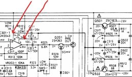
Regarding checking the power supply voltages, just to be sure, does this involve measuring the voltage of the marked points in the schematic screenshot below with the amp turned on and checking if the measured voltage matches the voltage indicated on the schematic? If so, is there anything I should watch out for to avoid accidentally ruining the amp with the multimeter leads - besides just not shorting anything? Lastly, how do I check the ripple levels? Is that related to the main amp alignment procedure on page 5 in the service manual?

Thanks for the advice. Firstly, I just realized that the 3240PE schematic I included in the original post looks a bit different to the 7240PE one (although it is purportedly the same amp section) so I've replaced it with the 7240PE service manual which includes its schematic on page 13.
I had already replaced the busted caps that I could see and touched up some random suspect solder joints earlier but I will do another thorough round of visual inspection to make absolutely sure everything looks in order.
Regarding checking the power supply voltages, just to be sure, does this involve measuring the voltage of the marked points in the schematic screenshot below with the amp turned on and checking if the measured voltage matches the voltage indicated on the schematic? If so, is there anything I should watch out for to avoid accidentally ruining the amp with the multimeter leads - besides just not shorting anything? Lastly, how do I check the ripple levels? Is that related to the main amp alignment procedure on page 5 in the service manual?
Yes you've got the right idea for measurement points. You measure ripple level with the oscilloscope. You have to be extremely careful with multimeter probes, it's so easy to slip and short something out.
One thing you can do is get some spring loaded hook on probes for your multimeter, then attach them to the desired measurement point when the amplifier is off. Then switch it on. Take the measurement and then turn it off. You can repeat this process for each measurement. This is fairly safe and far less prone to slippage, but it may pay to wait a 1 min before and after each measurement to allow the capacitors to discharge a bit. I use this method if the measurement points are not readily accessible.
One thing you can do is get some spring loaded hook on probes for your multimeter, then attach them to the desired measurement point when the amplifier is off. Then switch it on. Take the measurement and then turn it off. You can repeat this process for each measurement. This is fairly safe and far less prone to slippage, but it may pay to wait a 1 min before and after each measurement to allow the capacitors to discharge a bit. I use this method if the measurement points are not readily accessible.

@kapitiaudio, thanks for the hook-on probe tip. It's exactly the sort of precaution I was looking for.
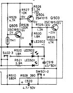
@Jakobsson, thanks for the advice. I'll order some replacements for C515-C520.
@Jakobsson, thanks for the advice. I'll order some replacements for C515-C520.
@kapitiaudio, while waiting for the capacitor replacements recommended by Jakobsson, I've checked the power supply voltages by measuring the voltage over capacitors:
20 V supply:
C517: 19.7 V
C518: 19.4 V
43 V supply:
C505: 40.2 V
C506: 40.4 V
71 V supply:
C509: 77 V
C510: 77 V
and I checked the +28 V point by measuring the voltage from the collector of Q501 to the negative leg of C513, this was 32 V. The -28V point is 31.7 V, measured from the collector of Q502 to the positive leg of C514.
Might we be able to deduce anything by the discrepancies present on the 28 V, 43 V and 71 V supplies?
Voltage over C520 controls Q201,Q302 which i beleive is the main cause of your warmup problem but i might be wrong.
Voltages seem sensible. Now also check the speaker outputs to see if there's any DC offset. After that, you'll need the oscilloscope to look at the power supply ripple levels and also to monitor what signal is coming out of the amplifier speaker terminals at startup.
@Jakobsson, I just switched out C515-C520 and the the startup ground-like noise is way quieter now and only goes for 1/3 as long as before so replacing them definitely seems to have had a positive effect even though it's still present. I appreciate the help nonetheless, thank you.
@kapitiaudio, I checked the DC offset, it seems to be around -85 mV on the right channel and 0 mV on the left. I have ordered a probe for my oscilloscope but it won't arrive for a few weeks. I'll post again on here about the supply ripple levels and the startup noise once I receive it and test with it.
@kapitiaudio, I checked the DC offset, it seems to be around -85 mV on the right channel and 0 mV on the left. I have ordered a probe for my oscilloscope but it won't arrive for a few weeks. I'll post again on here about the supply ripple levels and the startup noise once I receive it and test with it.
I have some Technics amplifiers that have to primary mains voltage settings that are quite close together. If you have similar options a previous owner might have chosen the highest of two close similar voltage ratings to extract more power output for your amplifier. I would query the ac winding for the 71volt supply. The risks of higher voltage supplies are greater than those of the lower supplies@kapitiaudio, while waiting for the capacitor replacements recommended by Jakobsson, I've checked the power supply voltages by measuring the voltage over capacitors:
20 V supply:
C517: 19.7 V
C518: 19.4 V
43 V supply:
C505: 40.2 V
C506: 40.4 V
71 V supply:
C509: 77 V
C510: 77 V
and I checked the +28 V point by measuring the voltage from the collector of Q501 to the negative leg of C513, this was 32 V. The -28V point is 31.7 V, measured from the collector of Q502 to the positive leg of C514.
Might we be able to deduce anything by the discrepancies present on the 28 V, 43 V and 71 V supplies?
@kapitiaudio, I checked the DC offset, it seems to be around -85 mV on the right channel and 0 mV on the left. I have ordered a probe for my oscilloscope but it won't arrive for a few weeks. I'll post again on here about the supply ripple levels and the startup noise once I receive it and test with it.
If the startup noise occurs on both channels, then the slightly high DC offset won't be the cause. Get the scope on the output, you need to see what's going on.
- Home
- Amplifiers
- Solid State
- Noisy NAD 7240PE - how to diagnose issue?