Hi I'm back
As you may have heard I have been working on a switch able pre-amp project for some time now. And now I have reached the point where my memory starts to fail me. I have been planning to try some classic SS CCS circuits and be able to switch from one to the other so I can make a direct comparison between them.
The stumbling block(s) are that I have two schematics which I would very much like to try but some of the resistor values are not stated. I have a B+ voltage maximum of 275v and a current of 80ma but I will be installing potentiometers to bring these down further (between back to back transformers 12v for the B+).
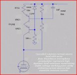
1.Wavebourn pnp cascoded ccs (good at blocking AC)
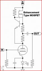
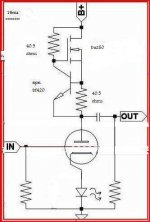
2.Nelson Pass aleph mosfet + transistor (can be made to produce a bass dynamic)
As you may have heard I have been working on a switch able pre-amp project for some time now. And now I have reached the point where my memory starts to fail me. I have been planning to try some classic SS CCS circuits and be able to switch from one to the other so I can make a direct comparison between them.
The stumbling block(s) are that I have two schematics which I would very much like to try but some of the resistor values are not stated. I have a B+ voltage maximum of 275v and a current of 80ma but I will be installing potentiometers to bring these down further (between back to back transformers 12v for the B+).
1.Wavebourn pnp cascoded ccs (good at blocking AC)
2.Nelson Pass aleph mosfet + transistor (can be made to produce a bass dynamic)
Attachments
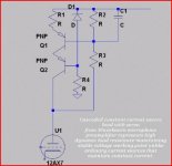
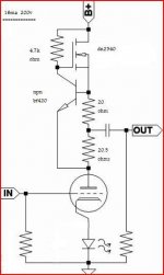
In both cases the current setting resistor (R1 in first picture and series combination of two resistors under that FET on the second picture) are calculated like this - I'll elaborate on right picture because left one is missing other key details (zener voltage):
dU = 0.65V (base-emitter voltage drop)
I = desired current that CCS supplies
R = dU / I
Collector resistor of right picture can be of just about any size that allows enough collector current to flow, 4.7K is just as good a choice as any.
dU = 0.65V (base-emitter voltage drop)
I = desired current that CCS supplies
R = dU / I
Collector resistor of right picture can be of just about any size that allows enough collector current to flow, 4.7K is just as good a choice as any.
thanks for your help........i make that about 40.5ohms for 16ma i will try a 50/50 split say 20ohms for the top resistor and 20ohms and a bit more on the tolerance band for the lower unless anyone can say better (ONLY AN EXAMPLE).
would a 1N5388B zener diode be over-kill for the diode i can only think that it maybe out of the range of the transistor base for ccs use.
would a 1N5388B zener diode be over-kill for the diode i can only think that it maybe out of the range of the transistor base for ccs use.
BTW, lose the bypass cap across the LED- it's useless in that spot.
A MOSFET cascode using depletion mode FETs will outperform just about anything.
A MOSFET cascode using depletion mode FETs will outperform just about anything.

thanks for your help........i make that about 40.5ohms for 16ma i will try a 50/50 split say 20ohms for the top resistor and 20ohms and a bit more on the tolerance band for the lower unless anyone can say better (ONLY AN EXAMPLE).
I'm not sure what author wanted to achieve there, but if it was me I'd use a single resistor and take output directly from the anode. You're losing some gain by splitting it in two, assuming the tube anode is biased exactly halfway into B+ in quiescent state.
would a 1N5388B zener diode be over-kill for the diode i can only think that it maybe out of the range of the transistor base for ccs use.
Yes, it would be. Zener diode only dissipates as much current as you allow it to and in order for it to stabilize at its nominal voltage 1 mA is more than enough. R4 will be the element that dissipates vast majority of power lost there, you can use any 1/2W 5.6V zener or even LED if you want less noise and don't mind tinkering with precise resistor value (LEDs, unlike zeners, don't come preselected for specific voltage drop ...).
Oh and DN2540 is not an enhancement type MOSFET. If you want to use that you can lose majority of componets there, you only need one resistor to set the current.
Last edited:


what sort of voltage rating do you think i would need of the transistor
PS..........and i made a mistake on the diode in the pic the voltage is not right
PS..........and i made a mistake on the diode in the pic the voltage is not right
bf762 350v 500ma 2sa1156 400v 500ma 2sa1626 400v 1A buw32a 400v 10A
or could it be something other than the transistors
or could it be something other than the transistors
Voltage drop is different in this case (way more than one Vbe that it was in the other pic) so too low a value will cause to much current to flow and your transistors to die.
Read: Current source - Wikipedia, the free encyclopedia
Read: Current source - Wikipedia, the free encyclopedia
Does the word "servo" say something? 😎
I think wavebourn is laughing in his sleep right now... 😀
I think wavebourn is laughing in his sleep right now... 😀
it's a form of governer feed back............i have stated in other posts that it's been 20 years since i've done any work on valve amps so all sand is new to me and thats the main reason i wish to start work on these CCS types as they are one that i remember.FROM WAY BACK
- Status
- Not open for further replies.
- Home
- Amplifiers
- Tubes / Valves
- no resistor values........