I'm a very novice level electronics guy but I'm a journeyman electrician with a specialty in controls and logic so maybe that will be enough for this project.
Parents gave me an old Hifonics Taurus X that my dad used to have in his car. The car, and the amp, both sat for an extended period of time (1-2 years) in the direct TX sun. External temperatures were surely over 110 F in the time frame, I can't imagine what the trunk would have been. He assures me it worked the last time he drove the car.
Tried hooking the amp up to my setup and no response. No power light, no protection light, no sound. Tried attaching directly to the battery (with fuse) and same scenario. Checked voltage to the terminals and 12v was present.
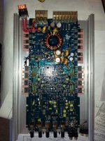
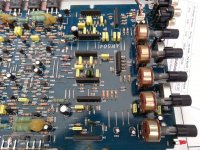
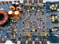
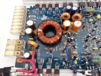
I opened it up and things weren't too bad. There was a brittle buildup on some terminals/parts of the board (see on some of the larger solder areas) so I used a pick to gently clean as much of it off as I could. I gave everything a very careful look and haven't noticed any burnt/melted items or solder bridges.
Looking for some help on the next step here. What are the first few things to check to see if this thing is worth fixing? I've got a DMM and experience using it but lack any other sophisticated equipment (oscilloscope, tone generator, flux capacitor, etc.).
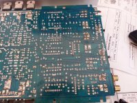
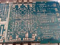
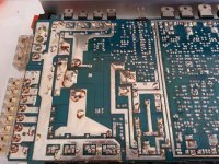
Took a lot of pictures of the board - hopefully they'll help. Flash was better for picture contrast but ended up with a blind spot in the middle. I've attached low res versions here and there are better versions and additional photos at the following links:
PDF Binder w/o Flash (18MB)
PDF Binder w/Flash (30MB)
Link to Full Dropbox Folder - Full resolution individual photos
Thanks!!
Parents gave me an old Hifonics Taurus X that my dad used to have in his car. The car, and the amp, both sat for an extended period of time (1-2 years) in the direct TX sun. External temperatures were surely over 110 F in the time frame, I can't imagine what the trunk would have been. He assures me it worked the last time he drove the car.
Tried hooking the amp up to my setup and no response. No power light, no protection light, no sound. Tried attaching directly to the battery (with fuse) and same scenario. Checked voltage to the terminals and 12v was present.
I opened it up and things weren't too bad. There was a brittle buildup on some terminals/parts of the board (see on some of the larger solder areas) so I used a pick to gently clean as much of it off as I could. I gave everything a very careful look and haven't noticed any burnt/melted items or solder bridges.
Looking for some help on the next step here. What are the first few things to check to see if this thing is worth fixing? I've got a DMM and experience using it but lack any other sophisticated equipment (oscilloscope, tone generator, flux capacitor, etc.).
Took a lot of pictures of the board - hopefully they'll help. Flash was better for picture contrast but ended up with a blind spot in the middle. I've attached low res versions here and there are better versions and additional photos at the following links:
PDF Binder w/o Flash (18MB)
PDF Binder w/Flash (30MB)
Link to Full Dropbox Folder - Full resolution individual photos
Thanks!!
Attachments
-
 2014-05-06 13.30.38.jpg170.6 KB · Views: 127
 -
 2014-05-06 13.38.51.jpg232.9 KB · Views: 79
 -
 2014-05-06 13.38.39.jpg247.9 KB · Views: 80
 -
 2014-05-06 13.38.32.jpg236.3 KB · Views: 115
 -
 2014-05-06 13.39.23-1.jpg244 KB · Views: 127
 -
 2014-05-06 13.39.18.jpg281.8 KB · Views: 118
 -
 2014-05-06 13.39.13.jpg236.9 KB · Views: 154
I'm assuming that you know that you have to connect B+, ground and remote turn-on.
If so, post the DC voltage on all pins of the 16 pin power supply driver IC. If you need help with the pin configuration, let us know. Copy and paste the following into your reply.
Pin 1:
Pin 2:
Pin 3:
Pin 4:
Pin 5:
Pin 6:
Pin 7:
Pin 8:
Pin 9:
Pin 10:
Pin 11:
Pin 12:
Pin 13:
Pin 14:
Pin 15:
Pin 16:
If so, post the DC voltage on all pins of the 16 pin power supply driver IC. If you need help with the pin configuration, let us know. Copy and paste the following into your reply.
Pin 1:
Pin 2:
Pin 3:
Pin 4:
Pin 5:
Pin 6:
Pin 7:
Pin 8:
Pin 9:
Pin 10:
Pin 11:
Pin 12:
Pin 13:
Pin 14:
Pin 15:
Pin 16:
I'm assuming that you know that you have to connect B+, ground and remote turn-on.
Definitely. For testing I've got a jumper to B+
Took the voltage readings but I'm wondering if I've done something strange. It's a TL494 chip. All reading taken with the black wire of the DMM on B-, red wire to the pin.
Pin 1: 12.2
Pin 2: 12.26
Pin 3: 12.18
Pin 4: 12.3
Pin 5: 11.9
Pin 6: 12.36
Pin 7: 12.39
Pin 8: 12.47
Pin 9: 12.4
Pin 10: 12.4
Pin 11: 12.4
Pin 12: 12.4
Pin 13: 12.39
Pin 14: 12.39
Pin 15: 12.39
Pin 16: 12.39
I've got a sinking suspicion I shouldn't have voltage on all of these pins. 😱
Thanks!
You don't have a ground. It's likely that the screw for the ground terminal block is loose.
Well tan my hide. After fiddling with everything on the top of the board for a while trying to figure out what the problem was I decided to flip it over.
Took a reading off the main lug to the main rail and found nothing there. Close inspection revealed that a hairline that I thought was a scratch was actually a break across the neutral rail.
Soldered a bridge between the two and now I've got a green light!
I'll get it hooked up later today and see how it works on the actual sound part of the equation.
Thanks Perry!
Attachments
I'll get it hooked up later today and see how it works on the actual sound part of the equation.
Thanks Perry!
Well, not very good it turns out. Hooked up the amp in the truck and got everything wired up. Hit the power and the subwoofer began pulsing in a heartbeat like pattern, with slow, extreme excursion. Red Protect light would pulse along with the beat. At the very minimum amount of gain/boost I could tell that it was reacting with the music but adjusting up would immediately started maxing out the cone.
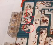
Cursory google search indicated an insufficient ground so I moved it to a nice piece of bare metal but still had the same problem. Opened it up and found a 200 Ohm 5% resistor that had burnt out. Not sure why or how. Was hot swapping between channels to see if that was the problem and may have grounded something out?
Picture of the blown resistor is attached along with a view from underneath showing the traces. When hooked to the power supply I've got a green light on and red light off.
Rechecked the IC and here's what I got:
Source Voltage - 11.7v
Code:
Pin 1: 2.49
Pin 2: 4.52
Pin 3: 0.97
Pin 4: 0.01
Pin 5: 1.56
Pin 6: 3.66
Pin 7: 0.00
Pin 8: 10.91
Pin 9: 4.3
Pin 10: 4.3
Pin 11: 10.91
Pin 12: 11.08
Pin 13: 4.98
Pin 14: 4.98
Pin 15: 2.42
Pin 16: 2.42
Hopefully I didn't FUBAR the thing when I was messing around with it, would hate to have gotten it to turn back on only to immediately fry it!
Anything someone can recommend to check before I replace the resistor?
Thanks!
Attachments
Quick note - Blown resistor is showing 230 ohm resistance while still in the circuit. Probably doesn't help much since it's still in the board but I thought I'd add.
Does one end of the resistor read 0 ohms to the main amp ground and other end read 0 ohms to all of the non-bridging speaker terminals?
Check this with nothing connected to the amp.
Check this with nothing connected to the amp.
Does one end of the resistor read 0 ohms to the main amp ground and other end read 0 ohms to all of the non-bridging speaker terminals?
Check this with nothing connected to the amp.
Can you clarify non bridging? Amp has 4 channels with 1/2 & 3/4 being bridgeable.
FWIW - Originally tested speaker bridged between 1&2, when I went only on channel 1 it required additional gain/boost to produce heart beat.
Thanks again!
The non-bridging terminals are all of the ones that go unused when speakers are connected in bridged mode.
Did you have all of the transistors tightly clamped to the heatsink when you were testing?
Did you have all of the transistors tightly clamped to the heatsink when you were testing?
Figured that out when I was taking measurements - was thinking in pairs!
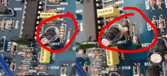
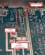
So, assigning the top leg in the pictures above #1 (downstream), the bottom leg #2 (upstream) and Bridged Terminals = BT:
I've got some 220Ω 1/2w and some 100Ω 1/2w that I could wire in series if it's worth using them for testing.
When I ran the live speaker test everything was in operating condition - only thing I'd left out were a few case screws. IC voltage and resistance testing have taken place without heatsinks but also with no load.
All help is very much appreciated!
So, assigning the top leg in the pictures above #1 (downstream), the bottom leg #2 (upstream) and Bridged Terminals = BT:
Code:
1 - > G = 230 Ω
2 - > G = 0 Ω

1 - > NonBT = 0 Ω
1 - > BT = 2.75k Ω

2 - > NonBT = 230 Ω
2 - > BT = 2.97k Ω
I've got some 220Ω 1/2w and some 100Ω 1/2w that I could wire in series if it's worth using them for testing.
When I ran the live speaker test everything was in operating condition - only thing I'd left out were a few case screws. IC voltage and resistance testing have taken place without heatsinks but also with no load.
All help is very much appreciated!
That resistor connects the primary and secondary grounds and isn't critical. Under normal operation, virtually no current flows through that resistor.
That resistor is most likely to burn if a bridging speaker terminal is allowed to contact the chassis ground of the vehicle.
That resistor is most likely to burn if a bridging speaker terminal is allowed to contact the chassis ground of the vehicle.
That resistor connects the primary and secondary grounds and isn't critical. Under normal operation, virtually no current flows through that resistor.
That resistor is most likely to burn if a bridging speaker terminal is allowed to contact the chassis ground of the vehicle.
Could this be the cause of the distorted sound and heartbeat? I ask because I'm fairly certain (but not 100% sure) that I had the problem before I tried moving the speaker wires around to different channels.
Is there any danger in using the 2 x 100Ω in series to run the speaker test again?
You can use either the 220 or the 2-100 ohms in series.
The low frequency pulsing can mean several things. It sometimes happens when the source unit has an open ground. It can also mean that the amp is going in and out of protect mode because there is excessive DC on one or more channels.
Check the shield ground of the head unit:
RCA Shield Repair
The low frequency pulsing can mean several things. It sometimes happens when the source unit has an open ground. It can also mean that the amp is going in and out of protect mode because there is excessive DC on one or more channels.
Check the shield ground of the head unit:
RCA Shield Repair
- Status
- Not open for further replies.
- Home
- General Interest
- Car Audio
- No Lights - Hifonics Taurus 4x50