
Try to simulate with a reactive load closer to a speaker, specially woofers.No global feedback from the power amp, just local feedback.
What are your thoughts?
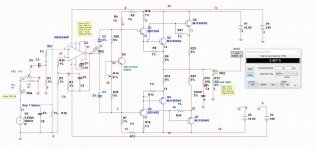
See image..i this right?
See below an example of a 4-ohm 10" woofer in a sealed 60-liter box I modeled for test purposes.
You can model a mid-range and tweeter and include the crossover too.
You can check THD at several frequencies and also sweep from 10Hz to 20kHz to see how your amp output voltage will behave according to impedance changes since there is no feedback to force the voltage to be stable.
I like low feedback amps, but none maybe is too radical and you might have DC offset issues.
Impedance curve of this circuit:
Do not believe a so called "reactive load" simulation could predict THD. May be the frequency response due to impedance change, but not much for THD. As long as the damping factor is not too low, it should not be an issue.ry to simulate with a reactive load closer to a speaker, specially woofers.
See below an example of a 4-ohm 10" woofer in a sealed 60-liter box I modeled for test purposes.
You can model a mid-range and tweeter and include the crossover too.
You can check THD at several frequencies and also sweep from 10Hz to 20kHz to see how your amp output voltage will behave according to impedance changes since there is no feedback to force the voltage to be stable.
I like low feedback amps, but none maybe is too radical 🙂
In simulation, caps and inductors are all ideal. Ideal caps and inductors don't affect THD, as they are linear passive components just as resistors. It gives no usable information regarding THD. If you target worst case 2 Ohm, just use 2 Ohm for the simulation.
One of the disadvantages of open loop amps is low damping factor.As long as the damping factor is not too low, it should not be an issue.
The idea is to check the behavior.
Resistors keep voltage and current in phase. Reactive load will force the current to be out of phase regarding the voltage and this is much more complex to an amplifier to drive. 2ohm resistive load is not equivalent to 2ohm capacitive or inductive.If you target worst case 2 Ohm, just use 2 Ohm for the simulation
Heat dissipation on output transistors will be different as well as transisition from NPN to PNP due to the not in phase voltage and current.
Zero voltage on output will not be zero current when using reactive load.
It's just a suggestion to test the idea in a closer (not exact) real world.
Thanks for the advise infoDo not believe a so called "reactive load" simulation could predict THD. May be the frequency response due to impedance change, but not much for THD. As long as the damping factor is not too low, it should not be an issue.
In simulation, caps and inductors are all ideal. Ideal caps and inductors don't affect THD, as they are linear passive components just as resistors. It gives no usable information regarding THD. If you target worst case 2 Ohm, just use 2 Ohm for the simulation.
Thanks for the adviseOne of the disadvantages of open loop amps is low damping factor.
The idea is to check the behavior.
Resistors keep voltage and current in phase. Reactive load will force the current to be out of phase regarding the voltage and this is much more complex to an amplifier to drive. 2ohm resistive load is not equivalent to 2ohm capacitive or inductive.
Heat dissipation on output transistors will be different as well as transisition from NPN to PNP due to the not in phase voltage and current.
Zero voltage on output will not be zero current when using reactive load.
It's just a suggestion to test the idea in a closer (not exact) real world.
Thanks to these recommendations..Try to simulate with a reactive load closer to a speaker, specially woofers.
See below an example of a 4-ohm 10" woofer in a sealed 60-liter box I modeled for test purposes.
You can model a mid-range and tweeter and include the crossover too.
You can check THD at several frequencies and also sweep from 10Hz to 20kHz to see how your amp output voltage will behave according to impedance changes since there is no feedback to force the voltage to be stable.
I like low feedback amps, but none maybe is too radical and you might have DC offset issues.
View attachment 1427630
Impedance curve of this circuit:
View attachment 1427631
- Home
- Amplifiers
- Solid State
- No global feedback from the power amp, just local feedback