I find myself in a strange position. I've been around this forum for years, I have a website with information on valve tech and I've spent most of my life around electronics. Despite this, I've actually built very little.
I've spent too much of the last 10 years living in other countries out of boxes to actually have a workbench set up, but I've finally got there in the last couple of months. I inherited quite a lot of equipment from my father (an EE) a few years ago, so I'm fairly well resourced, but I'm making newbie mistakes.
So I feel a little awkward, try not to laugh.
What I have is an RH84 amp breadboarded on my workbench. It works fine and sounds rather nice. Produces about 1.9W at onset of clipping, for 1.2VRMS in. Powersupply is an old bench unit (two outputs plus bias and heater supplies, etc), so I have a lot of flexibility.
What I noticed when poking around with an oscilloscope is that the input stage is the first to clip. So, I thought, why not use the powersupply and power the two sections separately. That way I can tweak the input stage without mucking with the output stage. So I've discarded the 10k resistor, 10uF cap and 22k resistor and I'm putting 160V (measured in circuit previously) directly on the plate of the 12AT7.
I now get no signal out of the 12AT7 and I don't understand why. I'm measuring signal at the junction of the 220R resistor and 0.22uF cap.
Anyone able to illuminate me?
In the end I will try and redesign the front end to use 6EJ7/EF184 as I have heaps of them and only two 12AT7, but there is a bit of learning to do to get to that point.
Attachments
lol ! thats the sort of thing I'd do! You just removed the resistor that provides the voltage signal...
Put the 22k resistor back in, and I think you will be good to go - at least you'll have a signal being developed.
Cheers
Put the 22k resistor back in, and I think you will be good to go - at least you'll have a signal being developed.
Cheers
Last edited:
hope that didn't sound too rude. Look at the circuit - the 22k resistor is one half of a voltage divider - the 12AT7 is the other. As the AT7 changes resistance, the voltage at the junction of the AT7 and the 22k resistor changes - this is your output voltage. Without the 22k, you get no voltage change, hence no signal.
Hope that helps a little more than my sophomoric schadenfreude.
Hope that helps a little more than my sophomoric schadenfreude.
Aaah. That makes sense. So the 10k resistor is a voltage dropper, the 10uF cap is additional filtering and the 22k resistor is as you describe. Am I correct?
Out of curiosity, how would the value of 22k be arrived at?
Out of curiosity, how would the value of 22k be arrived at?
It is not even close be optimal using a triode as driver in a Schaded/plate-grid feedbacked amp. The only relevant mod is to use a pentode at higher current as driver as your idea is. Parallelling the AT7 makes things worse as Ri gets even lower.
It is not even close be optimal using a triode as driver in a Schaded/plate-grid feedbacked amp. The only relevant mod is to use a pentode at higher current as driver as your idea is. Parallelling the AT7 makes things worse as Ri gets even lower.
I thought the ef184 he proposed is a pentode? And i dont see were he says that he wants to parallel the at7 halves?
Could he use a srpp first stage? Then he could use both halves of the at7, and at the same time increase max swing.
Or isnt that usable with a schaded/plate grid fb amp?
I thought the ef184 he proposed is a pentode?
As I said😉:
The only relevant mod is to use a pentode at higher current as driver as your idea is.
SRPP (The SRPP with its load-critical PP-function isn´t generally seen so particulary good in any placeIf wanting to go that route a high Gm pentode or MOSFET on top will be the better choice) is even worse as output impedance should be as high as possible to make the driver being a current amp.
Did a quick check at the curves for EF184 and a starting point could maybe be Ua 150V, Us 230V and Ik 15mA. Then it´s up to distortion-cancellation to do the rest😉.
10k is the CCS resistor (it helps to control the current to the ecc81)
10uf is to drain off any AC
22k is the anode-plate resistor
ecc81's will clip if pushed, if you used a ecc83 this would stop but you would need to keep the in-put under 500ma -ish
and change all the resistors via a datasheet
and reset the control grid of the el84 may-be
10uf is to drain off any AC
22k is the anode-plate resistor
ecc81's will clip if pushed, if you used a ecc83 this would stop but you would need to keep the in-put under 500ma -ish
and change all the resistors via a datasheet
and reset the control grid of the el84 may-be
ecc81's will clip if pushed, if you used a ecc83 this would stop but you would need to keep the in-put under 500ma -ish
and change all the resistors via a datasheet
and reset the control grid of the el84 may-be
Hey Pointy,
This make no sense. The plate-grid feedback makes the EL84 current input so the wimpy ECC83 won´t do at all. We need at last 5mA but preferably more ideally using a highGm pentode-driver as I mentioned before. The reason for is that the effictive Zin of the EL84 is below 2kohm. So using a triode will give substantial distortion.
Reading RDH4 that has a part(see below) dealing with this subject is a good starting point. The last sentence is essential, still a high-mu triode mentioned needs to be biased with maybe 10mA current. Still it will surely distort. Pentodes on the other side, needs a hard load to work properly.
A E280F or D3a would be great. The nice pentode section of the 6F12P would make the lowbudget alternative. And the thevoice´s EF184 will surely be a good start. Preferably it should also be fed by a gyrator/AC-CCS.
Attachments
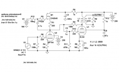
Hey thevoice,
This one will leave you with 4W at below 1% THD. The sim says 0,29% but we have to have some margin. Ie the EF184 is a very nice candidate for plate-grid feedback as predicted.
The schematic is not complete for IRL tests as you have to arrange the 155V and Us by yourself. V3 should be adjusted for a gyrator/Ua-voltage of 150V.
Attachments
i didn;t think he would try it ............just look at all the other sh''.. i listed to do with it
anyway what i was trying to say was yes ecc81's do that.
anyway what i was trying to say was yes ecc81's do that.
Hey thevoice,
This one will leave you with 4W at below 1% THD. The sim says 0,29% but we have to have some margin. Ie the EF184 is a very nice candidate for plate-grid feedback as predicted.
The schematic is not complete for IRL tests as you have to arrange the 155V and Us by yourself. V3 should be adjusted for a gyrator/Ua-voltage of 150V.
It was the work Christmas party last night, so at the moment I'll just say thanks. I'll have a better look and consideration in the next couple of days when I can see straight.

Thanks for everyone else's input also.
Hey Pointy,
Don´t want to be picky( 😉 ) but triodes aren´t that well suited even if they will work. THD of the AT7 should be in the ballpark of 10% but distortion-cancellation hides this somewhat.
What you want to make this type of feedback work best is a driver with infinite Ri. With the undecoupled cathode-resistor you rise the Ri (Ri´=Ri+(mu+1)Rk=23kohm) of the AT7 a bit but it is still comparably low wrt a pentode like EF184 that has 350kohm.
In general a pentode needs loading to work well and a triode works best without load. So with an Zin of ca 2kohm a pentode is to be prefered.
anyway what i was trying to say was yes ecc81's do that.
Don´t want to be picky( 😉 ) but triodes aren´t that well suited even if they will work. THD of the AT7 should be in the ballpark of 10% but distortion-cancellation hides this somewhat.
What you want to make this type of feedback work best is a driver with infinite Ri. With the undecoupled cathode-resistor you rise the Ri (Ri´=Ri+(mu+1)Rk=23kohm) of the AT7 a bit but it is still comparably low wrt a pentode like EF184 that has 350kohm.
In general a pentode needs loading to work well and a triode works best without load. So with an Zin of ca 2kohm a pentode is to be prefered.
Last edited:
whoops got it wrong again ................first time around i meet ef184
and just then i was thinking of the ecl 82
and just then i was thinking of the ecl 82
- Status
- Not open for further replies.
- Home
- Amplifiers
- Tubes / Valves
- Newbie questions - RH84 mods