OK, so I'm nearing finishing my four Chipamp.com LM3886 boards (stock, except for what I'm about to talk about). Again, no real knowledge of electronics here, just mostly soldering skills (and willingness to bang my head against the wall, apparently).
Now, I know that for my speaker load, I've been explained in clear terms that I need to change the gain, to 26dB. As I understand it, that means I need to change resistors. Since the Chipamp.com design is a non-inverting amplifier, I believe the appropriate formula to calculate gain is (Rf/R1) +1 .
Then I quickly asked myself what values of resistors I would need, cause dividing one number by the other doesn't exactly tell you what numbers you need, (not sure what I'm saying is clear). Lots of numbers, divided by other numbers yield the gain I want.
So, I know I want 26dB, how do I go about figuring out exactly which resistor values I need?
Thanks
Last edited:
A schematic would help. Usually the resistance the negative input sees should be close to the resistance the positive input sees.
Would thou parrot those clear terms to us; for i do not see, why one would need to set power amplifier gain according to load impedance? One usually keeps power amplifier gain fixed, and actual levels are set before or after it.
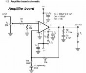
post4 pic looks like the sch shown in the National datasheet.
That sch is very misleading !
You have a number of missing circuits/components.
Add DC blocking to the input.
Add RF attenuating filter to the input.
Add output Inductor with it's damping resistor to the output
Pay attention to getting Cs close to the power pins and particularly getting the X7R VERY close to, or attached to, the power pins.
Ci is far too small to avoid distortion of the bass signals. and it's not optional !
And go read Tomchr for info on how to properly implement Cc connected to the -IN pin. If you don't do it that way then omit it completely.
Consider, as optional, adding RF attenuating capacitors to all the inputs and outputs.
and BTW,
the 25k vol pot is too high a value for the shown input impedance of 23k (1k+22k)
Use 10k maximum for 23k, or even increase to 40k (1k+39k)
Last edited:
Since the Chipamp.com design is a non-inverting amplifier, I believe the appropriate formula to calculate gain is (Rf/R1) +1 .......................
.
So, I know I want 26dB, how do I go about figuring out exactly which resistor values I need?
Thanks
For the diagram you posted the basic gain is (Rf/R3) + 1 which is 33. That is 30db. For 26db gain you need R3 to be around 1k1.
The resistors R1 and R2 form a voltage attenuator although the effect on overall gain from input to output is small.
Fwiw, running at higher gain can be beneficial in terms of stability and perceived subjective sound quality.
Andrews comments are all applicable and you should definitely AC couple the input (after the pot wiper) and add an output inductor and/or a small series resistor of up to 0.22 ohms.
you could start with 27k & 1k.............. appropriate formula to calculate gain is (Rf/R1) +1 ...........I know I want 26dB, how do I go about figuring out exactly which resistor values I need?.............
The 1k determines the noise added to the stage. It needs to be kept fairly low to limit that added noise.
Some go down as low as 100r just for noise reasons.
Some go higher than 4k7 just to avoid using an electrolytic in the lower feedback leg.
750r to 2k is probably a reasonable range.
26dB (=20times) is not the optimal gain for an lm3886.
Look at the gain/phase plot in the datasheet. 28db to 30dB gets into a range of stability margins that seem to be better. There are many here that recommend these slightly higher gains because it makes their amplifier sound better. What they are "hearing" is a slightly better HF response due to higher stability margins.
That 27k:1k ratio gets you to +28.9dB of gain, right in the "sweet spot" if such a thing exists.
But you could use 30k:1k1 or 33K:1k2 or 39k:1k3
This "tuning" of the lower NFB resistor allows you to set the roll off of the Ci capacitor. It needs to be a full decade lower than the lowest frequency you need your amplifier to process. If you need 20Hz capability, then The input filter must pass 2Hz and that requires Ci to be set to <1.4Hz An electrolytic here can be twice as big as the plastic for this duty, i.e. use 0.7Hz if electrolytic.
If 50Hz is low enough for your amplifier, then the input filter becomes 5Hz and the NFB should be set to <3.5Hz
R2 should roughly equal Rf to minimise the output offset when the Dc blocking capacitor is added to the input.
Last edited:
AndrewT:
Thanks for all that info, however:
1. I don't think you read my first sentence that I know next to nothing about electronics.
2. Are you saying that the schematic doesn't represent the Chipamp.com design?
I'm building stock, except for possibly the gain. I don't wish to add all kinds of other
mods/things.
Mooly: The formula I mentioned was given to me by Allan from Chipamp.com. This formula
is all over the Web. Can you explain why it's wrong with this circuit (assuming you're certain)?
Last edited:
I'm building stock, except for possibly the gain. I don't wish to add all kinds of other
I would just build the amp with the stock 30dB gain, and then you can turn down
the input volume control to compensate for the higher gain, if it is necessary.
Reducing the gain via the feedback resistor could cause problems that you don't want.
1) From Andrew: "26dB (=20times) is not the optimal gain for an lm3886.
Look at the gain/phase plot in the datasheet. 28db to 30dB gets into a range of stability margins that seem to be better."
If you don't understand, then trust that Andrew is correct.
2) No, it is (according to you) the Chipamp circuit. It is also the datasheet circuit. It is also incomplete.
Input DC blocking and Thiele network aren't "mods/things" they're necessary for a practical and useful circuit, no matter what the people at Chipamp say.
It's not wrong and Mooly didn't say it's wrong. Mooly (and Andrew) are pointing out that your choice of gain is not optimal for stability and distortion. And they are correct.
All three of us are veterans of this rodeo. If you don't understand, then you might consider taking our advice.
Look at the gain/phase plot in the datasheet. 28db to 30dB gets into a range of stability margins that seem to be better."
If you don't understand, then trust that Andrew is correct.
2) No, it is (according to you) the Chipamp circuit. It is also the datasheet circuit. It is also incomplete.
I don't wish to add all kinds of other
mods/things.
Input DC blocking and Thiele network aren't "mods/things" they're necessary for a practical and useful circuit, no matter what the people at Chipamp say.
Mooly: The formula I mentioned was given to me by Allan from Chipamp.com. This formula
is all over the Web. Can you explain why it's wrong with this circuit (assuming you're certain)?
It's not wrong and Mooly didn't say it's wrong. Mooly (and Andrew) are pointing out that your choice of gain is not optimal for stability and distortion. And they are correct.
All three of us are veterans of this rodeo. If you don't understand, then you might consider taking our advice.
if there is a particular sentence of phrase that your don't understand, there's two approaches. You go and research or you ask here.AndrewT:
Thanks for all that info, however:
1. I don't think you read my first sentence that I know next to nothing about electronics.
2. Are you saying that the schematic doesn't represent the Chipamp.com design?
I'm building stock, except for possibly the gain. I don't wish to add all kinds of other
mods/things.
Mooly: The formula I mentioned was given to me by Allan from Chipamp.com. This formula
is all over the Web. Can you explain why it's wrong with this circuit (assuming you're certain)?
I said that the sch looks like the National datasheet sch.
That datasheet sch is misleading.
Then I went on to tell you what was missing and what could be added as optional.
If you have the chipamp PCB and it really does use the chopped down version, then you need to consider carefully whether it is fit for use, or should be modified.
Did you download and look at the National sch to see how closely it resembles what you posted?
Did you read any of the datasheet for information on the missing circuits/components?
Did you do anything other than complain you know next to nothing?
Last edited:
I think these chipamp boards are intended for people that really know what they're doing. Everybody mods them. Nobody that understands these devices actually uses the chipamp suggested schematic. It is really just a "test" circuit.
To me, the virtue of products like this is that I don't have to make the boards myself. I hate making boards.
To me, the virtue of products like this is that I don't have to make the boards myself. I hate making boards.
Mooly: The formula I mentioned was given to me by Allan from Chipamp.com. This formula
is all over the Web. Can you explain why it's wrong with this circuit (assuming you're certain)?
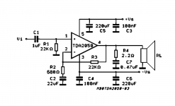
If you look at the component reference numbers on a circuit you will see everyone uses different numbering.
Look at this circuit from the TDA2050 data sheet. Here the gain is (R3/R2) + 1
Do you see 🙂
Attachments
I have used that Chipamp.com board in the past, if you assemble it stock as per instructions it will work but it can run into problems quite easily. Consider it a basic template.
At the very least use DC blocking caps at the inputs to avoid possible speaker damage from amplified DC.
People are trying to help you understand how to use this basic board and make a stable, safe amp from it. They are not trying to make life difficult for you, personally i welcome any help or advise i can get, even if i don't always understand it or act on it.
Last edited:
The manual answers the question:
"Lower the gain of the amplifier by varying R3 per the equation Gain = 1+ Rf/R3. The standard supplied gain set by R3 is 33dB. Gain should remain above 10dB to reduce the chance of the amplifier going into oscillation. To lower the gain, increase the value of R3."
R3Ci act as a high pass filter. So decreasing the frequency is normaly not a problem.
As of an input cap. At DC resistance, Ci is much larger than Rf, so Gain = 1.
Consider if your speakers can cope with the input DC value you have on the amp. An input cap would eliminate it completely.
(I agree with the others that the "protection" components are there for a reason. They make your amp work under all contitions and all enviroments. But maybe you are "lucky" and the chipamp works good enough as stock)
Last edited:
LM3886 has a minimum recommended gain of 10times, or +20dB.Gain should remain above 10dB
to maintain the stability margins.to reduce the chance of the amplifier going into oscillation.
Oscillation is different from overshoot of fast signals.
Chip amp manual ofcourse.
10 dB seems kind of low. Maybe a typo? TI says 20 to 40dB gain?
Anyway 26 dB is quite close to 30. Changing R3 to get 26 dB chould be OK.
Maybe the harmonics gets a little higher but only the selfproclaimed goldenears will hear. Harmonics will still be under -60 dB.
10 dB seems kind of low. Maybe a typo? TI says 20 to 40dB gain?
Anyway 26 dB is quite close to 30. Changing R3 to get 26 dB chould be OK.
Maybe the harmonics gets a little higher but only the selfproclaimed goldenears will hear. Harmonics will still be under -60 dB.
It's not only about absolute stability, but about transient response too. Transient response effects can be observed on a scope and are audible too. It depends on how much resolution your system has too. My current system is so coherent that when I listen to live recordings, if somebody in the audience coughs I turn and look because for a split second I think there's someone in the room coughing. Subtle changes in transient response in my prototypes are sometimes clearly audible when auditioned with this system.
Call me "goldenears" but I'm older with significant hearing loss, and I'm not superman. I have been messing with this stuff for 50 years so my ears are certainly "trained."
Call me "goldenears" but I'm older with significant hearing loss, and I'm not superman. I have been messing with this stuff for 50 years so my ears are certainly "trained."
Hm, can you really hear the difference between 26dB gain and 30 dB gain?
Adjusting for the extra 4 dBs ofcource?
I assume the chipamp does not measure worse than the XY kit with 26 dB gain.
http://www.diyaudio.com/forums/chip-amps/294032-xy-lm3886-kit-review-measurements.html
Adjusting for the extra 4 dBs ofcource?
I assume the chipamp does not measure worse than the XY kit with 26 dB gain.
http://www.diyaudio.com/forums/chip-amps/294032-xy-lm3886-kit-review-measurements.html
Last edited:
https://www.meridian-audio.com/meridian-uploads/ara/coding2.pdf
Page 25 states that normal ears can hear down to -63 dB 2. Harmonics. But that is at 60 dB where all implementations of lm3886 meassure excelent in normal systems.
I guess you need extensive listening experience with same high quality drivers and room to hear subtle changes in transient response of the amp. Do not doubt you have that, but you are one of the few lucky ones.
- Status
- Not open for further replies.
- Home
- Amplifiers
- Chip Amps
- Newbie question about gain resistors