Hello everyone!
I have decided to build a valve audio amplifier as part of my (late) middle life crisis management. It's been more then 40 years since I have done anything with valves, it's time to go back to the future 🙂
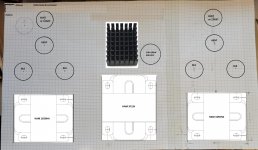
I'm looking to build a class AB1 stereo amp, based on 6L6 (6P3S-E) valves, been working on the component layout, and it would be great if you can comment on it. No need to be gentle, I can take punishment 😀
Thank you very much!
Jose
I have decided to build a valve audio amplifier as part of my (late) middle life crisis management. It's been more then 40 years since I have done anything with valves, it's time to go back to the future 🙂
I'm looking to build a class AB1 stereo amp, based on 6L6 (6P3S-E) valves, been working on the component layout, and it would be great if you can comment on it. No need to be gentle, I can take punishment 😀
Thank you very much!
Jose
Attachments
I have decided to build a valve audio amplifier as part of my (late) middle life crisis management.
Phew so I'm not the only one then.
Looks like a nice solid design with some beefy transformers. Around 12 Kilograms of Transformers so it's a heavy boy. Won't be bouncing around on any shelves.
I am still in the planning stage of my build and still trying to understand the finer details of PP circuits and what I can expect from my chosen Tubes being Russian GU-50 RF tubes.
Are you planning to make the chassis or buy it pre made?
Steel or Aluminium?
Are you planning to dress it up with any wood?
Sorry for so many questions. I get just as excited about seeing someone else's scratch build as I do about building one myself.
I look forward to updates on your build.
Subscribed to the thread now.
Best of luck with it Jose.
Last edited:
Thank you!That looks just fine. Transformer placement is also OK.
Phew so I'm not the only one then.
Looks like a nice solid design with some beefy transformers. Around 12 Kilograms of Transformers so it's a heavy boy. Won't be bouncing around on any shelves.
I am still in the planning stage of my build and still trying to understand the finer details of PP circuits and what I can expect from my chosen Tubes being Russian GU-50 RF tubes.
Are you planning to make the chassis or buy it pre made?
Steel or Aluminium?
Are you planning to dress it up with any wood?
Sorry for so many questions. I get just as excited about seeing someone else's scratch build as I do about building one myself.
I look forward to updates on your build.
Subscribed to the thread now.
Best of luck with it Jose.
Thank you, I'm sure I will need plenty of luck! My "experience" with valves is just my high school days in Cuba, scavenging old American TVs for transformers and valves. My knowledge was very basic, got plenty of electroshocks and red plates!
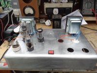
About your questions, I bought a Hammond aluminium chassis, 1444-30, from e-bay, they are reasonable priced, mechanical work was never my forte 🙂
The transformers, yes, they are a bit of an overkill, but I decided that I want something solid that allows modifications and upgrades in the future. I bought the lot from Digi-Key, and was delayed because my name and surname was found of a No-trade list of the USA government. After supplying all required information they went ahead and delivered the order.
Soviet GU-50's, takes me back to my university days in Odessa in the eighties, great looking tubes, especially when installed with the full enclosure. I was thinking about using GU-32's, but decided to go for the tried-and-tested 6P3S-E/6N7 set, they are well priced, and you can get matched quads.
I'm very exited indeed with this, will keep updating here with the progress.
The Russian 6Π3C-E (6p3s-E) is a nice 5881 equivalent.
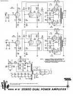
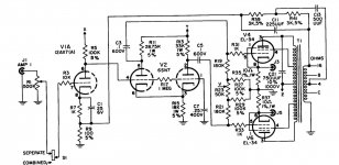
Hammond's 1650HA O/P transformer is a decent match for the 6Π3C-E. Given Hammond's reputation for OK, but not outstanding, performance, I suggest you employ "idiot resistant" Mullard style topology. IMO, EICO amps are good starting points. For cathode bias, see the HF87. For "fixed" bias, see the HF89.
Hammond's 1650HA O/P transformer is a decent match for the 6Π3C-E. Given Hammond's reputation for OK, but not outstanding, performance, I suggest you employ "idiot resistant" Mullard style topology. IMO, EICO amps are good starting points. For cathode bias, see the HF87. For "fixed" bias, see the HF89.
Attachments
The Russian 6Π3C-E (6p3s-E) is a nice 5881 equivalent.
Hammond's 1650HA O/P transformer is a decent match for the 6Π3C-E. Given Hammond's reputation for OK, but not outstanding, performance, I suggest you employ "idiot resistant" Mullard style topology. IMO, EICO amps are good starting points. For cathode bias, see the HF87. For "fixed" bias, see the HF89.
Thank you very much, that's quite useful. I definitely want to start with something relatively simple and idiot resistant. I'm going for cathode biased first, but also want to experiment with fixed bias, CCS, stabilised power source (cue the radiator), things like that.
.Soviet GU-50's, takes me back to my university days in Odessa in the eighties, great looking tubes, especially when installed with the full enclosure.
Yes I only hear everyone refer to those enclosures as a garbage can but I like the look of them. Quite unique as far as Tube Amps go. Mostly people seem to like the look of a bottle shaped tube with a ceramic connection on top.
The ones I have arriving are the original cast aluminium housing and look quite grey. I will most likely polish them up and either anodise the housing or do some kind of elecro plating on them.
Also the GU-50 has no base on them and the mount has a hole perfectly in the middle. Would be easy enough to centre mount a bit of artificial lighting in the base to make the tubes glow.
I pretty much decided on the old Mullard 5-20 design based on the success of others and hope to build something special out of it.
I don't have that much experience with building from scratch and have only repaired a few TV'S and radios till now.
It's a great hobby but fixing an AM radio only goes so far. Now I want a challenge and a show piece for my work.
With an aluminum chassis, add a piece of aluminum angle or channel to reinforce it - attach it with the output transformer mounting bolts so that it goes under the power transformer.
With an aluminum chassis, add a piece of aluminum angle or channel to reinforce it - attach it with the output transformer mounting bolts so that it goes under the power transformer.
I will take this into account, thanks! Is a 1.5 mm thick sheet, feels quite strong. Do you think it will bend? The transformers are close to the back wall. I put all of them on the chassis, I did not notice anything, measured at several points. Do you think it will bend with time?
1.5 mm needs to be reinforced.
..
Single supply filter caps are easier to replace and may be cheaper compared to duals.
..
Single supply filter caps are easier to replace and may be cheaper compared to duals.
1.5 mm needs to be reinforced.
..
Single supply filter caps are easier to replace and may be cheaper compared to duals.
Got it, I will do as you suggest, should not be difficult to attach to the output transformers.
About the filter cap, I got it already, but you are right, single caps are easier to find. For the rest of the stages I'm using axial ones.
1.5 mm might be OK, the usual Hammond 1 mm is definitely NOT...
Hmmm...looking at the datasheet is says 0.051" (1.3mm). I measured the real thing with a vernier caliper and I get very close to 1.5mm. I will add reinforcement just to be on the safe side.
If you want to see the surface bending - leave it as it is.
On the other hand this chassis is not very wide, so who knows ..
On the other hand this chassis is not very wide, so who knows ..
Last edited:
Aluminium tends to expand when heated unevenly. I have seen an amp where the heat from the tubes made the chassis buckle upward causing the section under transformers to sag a little.
I did see a build on YouTube where they reinforced the under side with 12mm Aluminium square tube in several places and then were also able to run some of the longer wires through it which helped shielding as well.
Can not find the link to that video.
He did show an amp though without the reinforced chassis that after 30 minutes operation made a loud popping noise as the metal expanded with the heat.
Funny though that his was the only video I saw make mention of this phenomenon.
But with 12kgs of transformers on the back you would probably want to reinforce it underneath.
My experience is from building air conditioning units with 1.5mm thick aluminium sheet though, not amplifiers
I've recently started a new amp and am using a Grundy roasting tin as the chassis, they can be bought new in the UK for about £30. They are solid ali, thickness about 2.5mm, see - Full size BS Tin - Grundy Tin it should fit your amp ok. The one I'm using I found chucked with some rubbish, it measures 16" x 10" x 3". The handles can be taken off (drill out rivits) and reversed. If you keep your eye out for auctions of catering equipment I think you could get a lifetime stash of chassis's.
Regarding your layout, try to keep in mind the signal input and heater wiring placement when orientating the valve bases. Try to keep IP wiring as short as possible, whilst not always possible an RCA IP right next to V1 is optimum. Also keep PSU wiring as short as possible too.
Andy.
Regarding your layout, try to keep in mind the signal input and heater wiring placement when orientating the valve bases. Try to keep IP wiring as short as possible, whilst not always possible an RCA IP right next to V1 is optimum. Also keep PSU wiring as short as possible too.
Andy.
Attachments
Last edited:
Wow Andy that's a great idea and even brand new are cheaper than buying a purpose built chassis.
The website fails to mention which one is for tube amplifiers though.
85mm - deep for food service
57mm - Lasagnes / shepherds pie
45mm - sponges
32mm - flapjacks
I might look out for something like this when I actually start my build.
I also want to replicate the old style filter caps with multiple values by stuffing them in some thin walled aluminium tube I have and putting the values on the outside with a printed water slide transfer.
If I went through all mums old 60's n 70's cake tins I could probably find chassis for 2 Mono Blocks and a Power Supply.
That's a great idea, and looks very good. I was browsing e-bay for used chassis or something similar, but I really did not think outside of the box like you did. Kudos!I've recently started a new amp and am using a Grundy roasting tin as the chassis, they can be bought new in the UK for about £30. They are solid ali, thickness about 2.5mm, see - Full size BS Tin - Grundy Tin it should fit your amp ok. The one I'm using I found chucked with some rubbish, it measures 16" x 10" x 3". The handles can be taken off (drill out rivits) and reversed. If you keep your eye out for auctions of catering equipment I think you could get a lifetime stash of chassis's.
Regarding your layout, try to keep in mind the signal input and heater wiring placement when orientating the valve bases. Try to keep IP wiring as short as possible, whilst not always possible an RCA IP right next to V1 is optimum. Also keep PSU wiring as short as possible too.
Andy.
About the input, this is something I'm still trying to decide. If I use a dual pot, it means cabling from the input tubes to the pot, which will be located right in the middle of the front panel, then it will make sense to also have the RCA sockets next to it. Alternatively, I could have separate pots for each channel, then is easy, all very close to the first stage tube for each channel. I need to make my mind about this, any ideas? Does shielded cable works OK to suppress noise if I use longer IP cables?
Edit: What is that tube on the left that looks like a Dalek?
Jose
If you want to see the surface bending - leave it as it is.
On the other hand this chassis is not very wide, so who knows ..
I already made my mind, ordered a 2.5mm angled aluminium strip to use for reinforcement. I did not take into account that valve amps get quite hot... I believe this is the danger here.
- Home
- Amplifiers
- Tubes / Valves
- Newbie looking for advice on stereo amp layout