Ok Guys, I'm still on the very basics here.
As amp to speaker matching is quite critical, has anyone (historically or otherwise) used a variac sort of arrangement for output transformers, to enable an amp to be adjusted based on partnering speakers?
If not, is the issue one of poor resultant signal transmission, or something else?
As amp to speaker matching is quite critical, has anyone (historically or otherwise) used a variac sort of arrangement for output transformers, to enable an amp to be adjusted based on partnering speakers?
If not, is the issue one of poor resultant signal transmission, or something else?
Amplifier to speaker matching is not critical.
Start again.
One simply has to ensure that the rated impedance of the speaker is not less than the rated load impedance of the amplifier.
Start again.
One simply has to ensure that the rated impedance of the speaker is not less than the rated load impedance of the amplifier.
1) it´s not *that* critical.
2) anyway speaker impedance varies wildly all over the place so exact matching becomes "acceptably close" at best.
3) that said, usual 2:1 steps (2/4/8/16 ohms) are close enough.
2) anyway speaker impedance varies wildly all over the place so exact matching becomes "acceptably close" at best.
3) that said, usual 2:1 steps (2/4/8/16 ohms) are close enough.
The dumb blonde one here tried connecting a Variac across the 16 ohm secondary of a 6600 to 0-4-8-16 OPT in a working amplifier maybe 30 years ago. As stated the exact match isn't that critical, and a common 6 amp Variac will not pass much high frequency information.
My current recommendation is choose a transformer that comes closest to the impedance marked on your speakers, then try every available tap and choose what sounds best to you.
My current recommendation is choose a transformer that comes closest to the impedance marked on your speakers, then try every available tap and choose what sounds best to you.
I was going from the example given in the crowhurst book, that a 20 ohm load instead of an expected 16 ohm load dropped the amp's output power 20%, and thought that was considerable enough to ask the question.
I know VTL use 5 ohms for their amps, but I don't know how they decided upon that figure.
I know VTL use 5 ohms for their amps, but I don't know how they decided upon that figure.
Could use 4 x 1 Ohm secondary windings to get (series/parallel) 1,4,9,16 Ohm.
Or use 6 x 0.5 Ohm windings to get (series/parallel) 0.5, 2, 4.5, 8, 12.5, 18 Ohm.
Since these are all acting like an output volume control, could just build a bigger amplifier, and use the input volume control knob.
One good reason to make a 75 Watt DCPP amplifier when you only need 25 Watts. Cost of the bigger OTs and Xfmrs doesn't increase that much over smaller ones, same labor charges. Put the Variac on the B+ then (for efficiency).
Last edited:
I have to dig for it but Mcintosh had a nice white paper on their output autoformer. It was used on solid state and vacuum tube units. I have never really fully understood that concept relative to audio transformers.
The Mac OT is like two Circlotron windings on one OT, so that only a single non-floating B+ is needed. Doesn't do much for variable output Z.
However, that just gave me an interesting idea. The problem with a Variac OT is the unused portion of the variable winding is causing increasing leakage L.
So, lets use the -whole- Variac winding. Let the Variac determine how much winding is used for the CFB portion, and the rest of it for the plate winding. That will vary the output Z without causing leakage L. (plate portion driven by the high Z plate, and the CFB portion driven by the low Z cathode) Some more thinking on this required no doubt for P-P. But very interesting conceptually. (unfortunately, the Variac operation has to apply to the high turns primary side for this, but could just use a reduced set of useful primary taps and a rotary switch.) Secondary has to be wound for the maximum output current case (wire size). And the amplifier needs to be over-sized again to handle variable primary current. Not doing any better than just an over-sized amplifier.
.
Last edited:
Looks like a low Z (low V, high current) Variac could be positioned -between- two secondary output taps from an OT. (say 4 Ohm and 8 Ohm taps, other side of the speaker still goes to the 0 secondary tap) That way the full Variac winding is still being used in an autoformer mode. Less of a leakage L problem then. Could move the Variac to different adjacent tap points for range changes.
Probably not very useful for the usual 0, 4, 8, 16 Ohm secondary OTs. But for say an OT with just two 4 Ohm windings (4 or 16 Ohm parallel/series configurable), could be useful to get in-between Zout.
Could also just use a LV fixed center tapped (or multi-tapped) autoformer to get intermediate Zout taps the same way.
This can go further. Just put the autofomer windings onto the OT.
Or better, provide a set of course adjust series/parallel secondaries, and another set of fine adjust series/parallel secondaries. Will be a nightmare to configure them dynamically, but in theory, efficient low leakage L operation, over a highly variable range of Zout, would be possible. (always using -all- windings in each set in parallel/series combos) The Xfmr winders will not like this though. (too many secondary wires)
More simplified, and practical:
Provide the usual set of course adjust series/parallel windings ( 4 of 2 Ohm windings for 4, 9, 16 Ohm selection), with multiple fine adjust tap points on -one- (or two) of the sub windings.
(maybe just CT points on two of the 4 sub 2 Ohm windings, giving 4, 6, 9, 12, 16 Ohms for two extra secondary wires, a total of 10 secondary wires )
Hmm, can reduce that Further!
Just use two 4 Ohm secondary windings, with center taps, and a 1/4 tap on one end of each. Still 4,6,9,12,16 Ohms selection at full coupling efficiency, but only 8 secondary wires now. (give me another day to get it down to 6 wires - still at full efficiency coupling, not just serial taps 🙂 )
.
Last edited:
1W into 16ohms equates to 4Vac. 0.8W (80% of 1W) into 20ohms equates to 4Vac.I was going from the example given in the crowhurst book, that a 20 ohm load instead of an expected 16 ohm load dropped the amp's output power 20%, and thought that was considerable enough to ask the question.
I know VTL use 5 ohms for their amps, but I don't know how they decided upon that figure.
An apparent drop of 20% in power capability when raising the load impedance by 25% indicates that the output voltage is IDENTICAL for the two arrangements.
True.1W into 16ohms equates to 4Vac. 0.8W (80% of 1W) into 20ohms equates to 4Vac.
An apparent drop of 20% in power capability when raising the load impedance by 25% indicates that the output voltage is IDENTICAL for the two arrangements.
What roughly applies to SS amps, which do not use OTs an is definitely not the case on Tube amps, which do.
What makes me think that Crowhurst´s example was just a "class room example" and not much should be extrapolated from it.
I was going from the example given in the crowhurst book, that a 20 ohm load instead of an expected 16 ohm load dropped the amp's output power 20%, and thought that was considerable enough to ask the question.
I know VTL use 5 ohms for their amps, but I don't know how they decided upon that figure.
In the big picture of things, exact matching of output impedance isn't very important indeed. Less power and/or more distortion is the consequence of mismatch, and it is a matter of taste how much of those things one is willing to accept.
However, if the goal is to carefully optimize distortion vs. power, load matching is important. Some tube data sheets provide graphs for power and different order distortion vs. load at various operating points, which show how the load can be optimized to achieve design goals.
As to the argument that speaker impedance changes with frequency, there are speakers whose impedance doesn't change much.
Using 7 secondary wires now, I can get 4, 6, 8, 12 and 16 Ohm output with efficient secondary winding use:
Two 4 Ohm windings, each with a center tap, and one of those with a 1/4 tap.
Using 8 secondary wires, can get 4, 5, 6, 7, 8, 10, 12, 14, and 16 Ohm outputs efficiently utilized:
Use two 4 Ohm windings, each with a center tap, and one of those with a 1/4 tap and a 1/8 tap.
Could ratio any of these to a different range, like 2 to 8 Ohm, or 8 to 32 Ohm (still 9 selections)
Last edited:
'Gentlemans',
I am reluctant to disagree with Smoking-amp and even more so with Crowhurst, but .....
Not sure that any commercial variac would do on the secondary side of things - too high a d.c. resistance in the windings, even a specially wound one. Regarding Crowhurst - mmmm. I have not calculated but frown somewhat; at least, graphs will show that the output of a tube amplifier changes much less when working into a too high impedance than a too low one. Distortion similarly.
Normal loudspeaker impedances I recall vary by > factor 1,5:1. Sser2, can't recall that I have ever seen a loudspeaker impedance being more constant than x 1,5, often less constant. I do however not have extensive experience.
Bottom line for me: For normal domestic use I would not worry about a load variation of 1,5:1. Important though, as was said, is that in adjusting to different output impedances, all of the (secondary) windings should always be utilised. (The original Williamson OPT is an example of this.)
I DO agree on the impracticality of a Variac on the secondary. I often just conduct a thought experiment to see what might work and where it might lead, and then look at what would need fixing to make it actually work. While a custom, LV high current Variac might be made to interpolate between OT taps, the typical carbon brush would put too much resistance in series for saving the damping factor, unless the Variac were some huge unit (and expensive as HLL). ( I do have a 50 Amp Variac, but it is so big and heavy, it takes a geared motor to turn the brush.)
The idea of interpolating between two secondary taps then led to the idea of a course and fine adjustable set of secondary windings. Which IS looking practical, just a bit excessive on # of secondary wire leads. If Edcor ever re-instates the custom OT offerings, I probably would try the 7 or 8 wire 4, 6, 8, 12, 16 Ohm secondary idea. Also, always requesting that the CT of any primary be brought out as two separate wires.
The practical solution in the mean time is to just make the amplifier bigger than needed, which is easy with cheap TV Sweep tubes. (speaker loading insignificant) A Variac on the B+ supply might still be useful for economizing power consumption during quiet listening sessions. (as long as the Variac does not hummm).
Last edited:
Auto-transformers are available as in-wall volume controls. You may use one for your experiments.
> amp to speaker matching is quite critical
Don't listen to innernet chatter from guys like Andrew, JM, orTubeLab. And especially that kook PRR.
Do tests. If you lack test facilities, use some of the heaps of old hand-compiled data collected when tubes were mainstream.
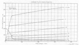
I attach the flawed data for 6V6. It needs a Torah's-worth of interpretation, but is not wrong. Going 25% either way from "book suggestion" gives very slight power difference, maybe 1dB (not 20%/2dB). If you are just 1dB short of your goal, you don't need 1dB, you need twice the tube so you are not so close to coming out short. Likewise the THD numbers (AT that point) can all be covered with one thumb.
Don't listen to innernet chatter from guys like Andrew, JM, orTubeLab. And especially that kook PRR.
Do tests. If you lack test facilities, use some of the heaps of old hand-compiled data collected when tubes were mainstream.
I attach the flawed data for 6V6. It needs a Torah's-worth of interpretation, but is not wrong. Going 25% either way from "book suggestion" gives very slight power difference, maybe 1dB (not 20%/2dB). If you are just 1dB short of your goal, you don't need 1dB, you need twice the tube so you are not so close to coming out short. Likewise the THD numbers (AT that point) can all be covered with one thumb.
Attachments
The 6V6 distortion curve PRR posted above is for class A, single tube operation I believe.
When going to P-P (class A or AB1) the 2nd harmonic distortion will cancel out, which was causing most of the high distortion at low Z primary (left side) on the 6V6 SE graph (from gm variation versus current).
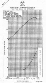
Here is a 6973 tube distortion graph for class AB P-P versus load Z. Notice the lack of the left side incline (low Z primary distortion) now. What is remaining are the remaining odd harmonics: from screen grid current distortion (curved individual plate curves, affects more at high Z) and gm curvature with current (decreasing with higher Z). [Normally there would still be some smaller incline in the distortion on the left side, with lower Z loading from gm variation, not the flat line shown here. Maybe this tube is exceptionally close to square law (Vg1 to Ip) for its gm curve, ie mostly 2nd Harmonic gm dist., which cancels in P-P]
http://tubedata.milbert.com/sheets/049/6/6973.pdf
I've seen some tube data sheets that show the individual harmonic distortions versus load Z, but I don't recall which tube datasheets had that.
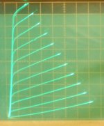
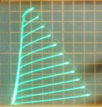
Using Twin/Crazy Drive for a TV Sweep tube produces near constant gm versus loading (load line tilt) with straight plate curves. (2nd pic) So loading accuracy is a non issue there. (there is still max power variation versus Z load though)
When going to P-P (class A or AB1) the 2nd harmonic distortion will cancel out, which was causing most of the high distortion at low Z primary (left side) on the 6V6 SE graph (from gm variation versus current).
Here is a 6973 tube distortion graph for class AB P-P versus load Z. Notice the lack of the left side incline (low Z primary distortion) now. What is remaining are the remaining odd harmonics: from screen grid current distortion (curved individual plate curves, affects more at high Z) and gm curvature with current (decreasing with higher Z). [Normally there would still be some smaller incline in the distortion on the left side, with lower Z loading from gm variation, not the flat line shown here. Maybe this tube is exceptionally close to square law (Vg1 to Ip) for its gm curve, ie mostly 2nd Harmonic gm dist., which cancels in P-P]
http://tubedata.milbert.com/sheets/049/6/6973.pdf
I've seen some tube data sheets that show the individual harmonic distortions versus load Z, but I don't recall which tube datasheets had that.
Using Twin/Crazy Drive for a TV Sweep tube produces near constant gm versus loading (load line tilt) with straight plate curves. (2nd pic) So loading accuracy is a non issue there. (there is still max power variation versus Z load though)
Attachments
Last edited:
Late addition.
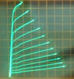
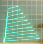
Here is the same tube (26LX6, as the 2nd pic above) with normal grid 1 drive. Placing any load line on this graph will show the obvious gm variation versus loading (ie, versus load line tilt).
Increased curvature in the individual plate curves also indicates/causes screen grid current distortion here too (ramping distortion at high Z loading). Although this tube has fairly straight plate curves where it counts.
If you believed tube manufacturer's datasheets, this (2nd pic, 6HJ5) would be the most linear tube on the planet (straighter than straight plate curves) when assisted by using Twin/Crazy drive to even out the gm. But, reality is not quite this impressive. (3rd pic, 6HJ5 using Twin/Crazy drive) Still a little curvature in the plate curves yet. Maybe this (4th pic, once a $1 tube) can claim that title.
Attachments
Last edited:
- Status
- Not open for further replies.
- Home
- Amplifiers
- Tubes / Valves
- Newbie basics - variable output transformer