hi,
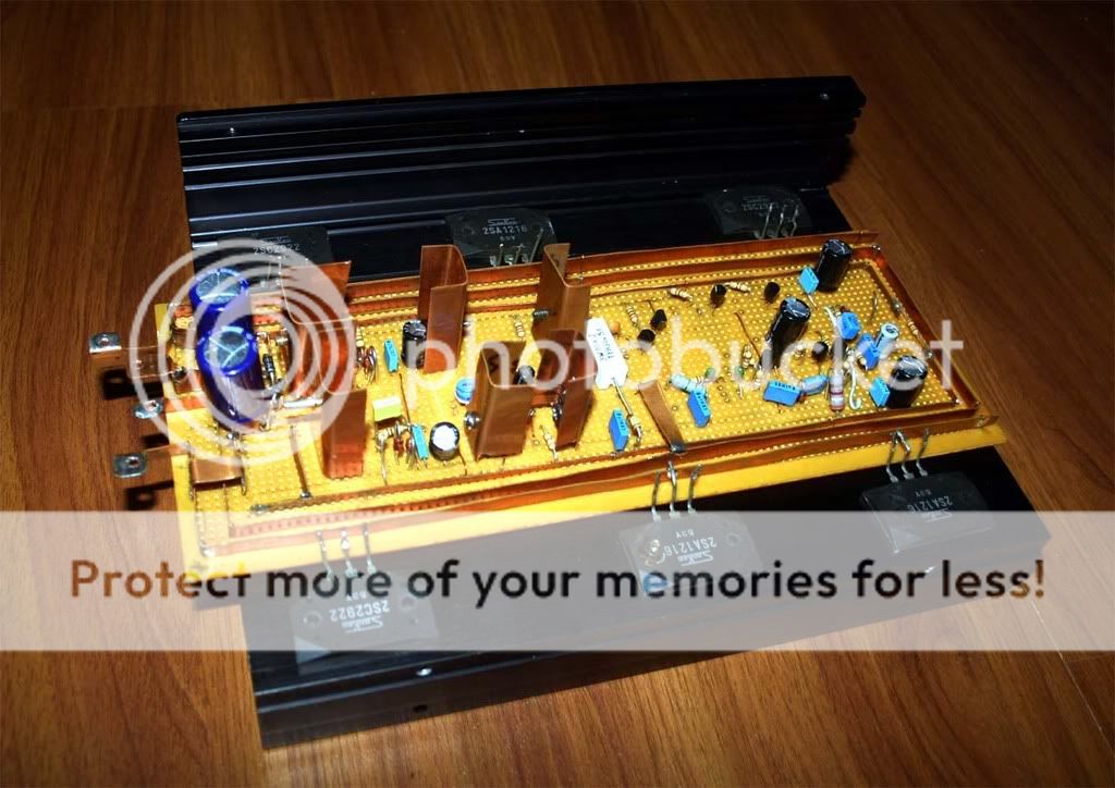
I am trying my DX-prec I to resconstruct. just made a circuit and the transistors are just placed to show how it's looks...it' not final yet. i just want to know is this way should be working fine? or anythings should be need to change?
i don't mind you can say ugly or anythings at all. all i need is to learn more about that i am doing it right or wrong. i am not an electronics engineer so can't do pcb board, only easy for me is to use vro board. i need more comments pls. anyone can write anythings at all. i value all of your comments.
thank you,
michael
for vero board
its more or less perfect .....
but if you calculate all this time and componets spent to make this you could just as well desing a pcb for it that will be 100% better and correct ....
any way since i know this is not a 5minute job and project like that is more than one day of work ....
well done !!!!!
Another work of art!
Either two of those output transistors are in the wrong location in the photo, or I cannot figure out how the wiring is routed. I suspect they are just posing for a photo.
Michael, you must try etching your own PCBs. I think it must be easier than this. Keep up the good work. It's going to sound great.
..Todd
hi, beside big cap two transistors are driver for 2sc2922 and 2sa1216.
output transistor you have seen, it was just to show how they are placed.
thank you for your advice.
michael
output transistor you have seen, it was just to show how they are placed.
thank you for your advice.
michael
Hi Space,
You don't have to be an electronics engineer to make a PCB. Give it a go, it can be as easy or as sophisticated as you want. A hand drawn board would be fine for this, use transfers for pads and I/C's. The cost is minimal - give it a try 🙂
Regards Karl
You don't have to be an electronics engineer to make a PCB. Give it a go, it can be as easy or as sophisticated as you want. A hand drawn board would be fine for this, use transfers for pads and I/C's. The cost is minimal - give it a try 🙂
Regards Karl
hi,
i got copper from metal shop. actually they are selling as big pc but i requested small pc. its depend on the chicknes. price not really very cheap. they are bit expensive when you buy small pc.
i got copper from metal shop. actually they are selling as big pc but i requested small pc. its depend on the chicknes. price not really very cheap. they are bit expensive when you buy small pc.
Here's a link to the PCB layout, and also the parts layout file in the following message. There are lots of methods to use it for etching your own DIY boards. Just search DIYAudio or Google, you'll see.
http://www.diyaudio.com/forums/showthread.php?postid=1478414#post1478414
..Todd
http://www.diyaudio.com/forums/showthread.php?postid=1478414#post1478414
..Todd
- Status
- Not open for further replies.
- Home
- Amplifiers
- Solid State
- New looks for 123w DX-prc I amp