What is the latest opinions for a TDA1541 tube stage?
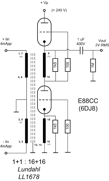
The only scheme I believe I have seen that doesn't violate the 25mv voltage compliance is the Laszlo's PP:
http://www.diyaudio.com/forums/attachments/digital-source/83747d1176897162-laszlos-valve-output-stage-lundahl-transformer-dac_tubeout.jpg
Unforunately it actually outputs 4Vrms which is too much. But it seems to be a design that could be perferected and more popular. Why has this stage met such obsucrity?
As far as SE, there of course a lot who use an I/V resistor that violate the 25mV compliance. I am not there yet, my own experience with PCM1704 and PCM63K is that this is a big compromise. I have tried a low ohm passive I/V + Cinimag mic step-up + 6n6p with a PCM63K, but the results weren't good, ie a bigger I/V resistor replacing the tranny was much better.
Has anyone built a TDA1541 output stage with a 6 ohm I/V + 6922+6922 parafeed output?
I mean it has become common for 6922 MMC preamps which output roughly 4mV rms. Why not do roughly the same thing but with the 25mV I/V resistor TDA1541a DAC? It seems so obvious but I have never seen any reports or trials, if the 6922 has a noise equivilancy of 300 ohms, I would think with the SSHV that SNR could be fine. Heck the MMC preamps have to deal with the RIAA eq, which wouldn't be required with a DAC, so the results should be better.
Anyone think this is worth persuing? The alternative is of course a zero NFB discrete I/V, but these typically have almost has much 2H distortion as a tube and filtering just isn't as elagant as iron.
Last edited:
This is what I am trying to decide on building vs using a 1:10 cinemag input transformer with the passive IV and only one tube gain stage. I guess I would prefer the two gain stage idea simply because I don't have to come up with a scheme to kill the 2ma DC offset to be able to use the step-up transformers.
I know a lot of builders (as in overwhelming majority) just ignore the max 25mV voltage compliance spec when using a tube stage after the TDA1541A, but if one is going to all the trouble to DEM reclock, I2S input, etc, it seems crazy to dump the TDA1541A output into a 50 ohm I/V resistor (I know any design is a compromise though.)

I know a lot of builders (as in overwhelming majority) just ignore the max 25mV voltage compliance spec when using a tube stage after the TDA1541A, but if one is going to all the trouble to DEM reclock, I2S input, etc, it seems crazy to dump the TDA1541A output into a 50 ohm I/V resistor (I know any design is a compromise though.)
Try a common grid stage.😎
Edit: seems not a good idea. Input impedance way too high....
http://www.diyaudio.com/forums/digital-source/121022-common-grid-i-v-converter.html
Edit: seems not a good idea. Input impedance way too high....
http://www.diyaudio.com/forums/digital-source/121022-common-grid-i-v-converter.html
Last edited:
Try a common grid stage.😎
Edit: seems not a good idea. Input impedance way too high....
http://www.diyaudio.com/forums/digital-source/121022-common-grid-i-v-converter.html
The input impedance is 5 ohms (load seen by the 1541)! Much lower than any common/grounded grid scheme.
This is an order of magnitude lower than a typical tube DAC stage. Not saying it is unique, it is a very typical topology for mm preamps, just can't understand why its not used for DAC's? I mean it is such a common scheme to amplify low amplitude signals, yet I have never heard of anyone trying it with a DAC, why ??
.
Last edited:
I don't like the two stage circuit much. Why don't you use a higher mu tube like a D3A, E280F, etc and a cap coupled output?
I don't like the two stage circuit much. Why don't you use a higher mu tube like a D3A, E280F, etc and a cap coupled output?
D3A is not even close for a single stage. There really aren't any single tubes with enough gain to accept a 25 mV input and output 2Vrms and have enough transductance to drive an amp or preamp with the typical 50k input imp.
You would have to find a tube with about gain around 200 and an Rp under 5k, ain't going to happen. I think there is an oddball russian tube that has a triode section of mu=100 Rp~5k and another section is a tetrode, but my understanding is it is inconsistant and not worth the trouble. And the output output would still only be 1Vrms.
I original didn't like the 2 tube solution either, but again most preamps are like this, and I would think there would be some 2H cancellation. Could also drop the cap between stages and DC couple with a higher B+.
But I am not sure this is better than using a stepup transformer, I've played with these 1:10 Cinemag mic input transformers but there just seems to be issues with impedance matching, dealing with a -30dBU signal, primary inductance, Dac i-out output impedance, etc. Most all are designed for either a 50ohm output impedance source or a 200 one (mics.) Multibit Dac chips usually have 1k to 2k output impedance which I think is the issue with the transformer IV trials.
Yes sure it's 5-Ohm. But it's passive IV-conversion, which I don't like (flat, non-dynamic sound)The input impedance is 5 ohms (load seen by the 1541)! Much lower than any common/grounded grid scheme.
This is an order of magnitude lower than a typical tube DAC stage. Not saying it is unique, it is a very typical topology for mm preamps, just can't understand why its not used for DAC's? I mean it is such a common scheme to amplify low amplitude signals, yet I have never heard of anyone trying it with a DAC, why ??
.
I wonder what Zanden is using in their 5000 DAC. They use a single 7308 tube. All other tubes in their unit seems to be rectifiers.
Anyway for common grid stages we must move to FETs. See Nelson Pass, Ecdesigns... Common gate properly named.
Hi,
You can also try the super common grid valve I/V converter with an input impedance < 1Ω (theorically <0,1Ω but I can not measure it). Output is 2Vp with 2kΩ output impedance. The good point is you do not need a pre-amp, just maybe a filter to suppress the 44,1kHz noise at output.
greg
You can also try the super common grid valve I/V converter with an input impedance < 1Ω (theorically <0,1Ω but I can not measure it). Output is 2Vp with 2kΩ output impedance. The good point is you do not need a pre-amp, just maybe a filter to suppress the 44,1kHz noise at output.
greg
Yes sure it's 5-Ohm. But it's passive IV-conversion, which I don't like (flat, non-dynamic sound)
I wonder what Zanden is using in their 5000 DAC. They use a single 7308 tube. All other tubes in their unit seems to be rectifiers.
Anyway for common grid stages we must move to FETs. See Nelson Pass, Ecdesigns... Common gate properly named.
I'm guess you don't like passive I-V because all you have heard are big resistances which takes the max voltage compliance on i-out above 25mV (max recommended per datasheet). With a small 5 ohm I-V resistor it is actially a lower impedance than what say a jfet would place on i-out.
I agree that a large resistance on i-out steals dynamics with multibit DAC's. I have heard this with a Jfet version of D1 which had an load of 50 ohms, gave the same sort of flatness that a 50 ohm passive I/V resistor did, That is why I am proposing this tube scheme.
Hi,
You can also try the super common grid valve I/V converter with an input impedance < 1Ω (theorically <0,1Ω but I can not measure it). Output is 2Vp with 2kΩ output impedance. The good point is you do not need a pre-amp, just maybe a filter to suppress the 44,1kHz noise at output.
greg
Greg, that is very interesting, always had an intuition that a pentode could be useful.
But this is designed around a TDA1543, I am trying to get my head around how I would input the TDA1541 Iout to the +3V at the cathode, I know the TDA1541 has 2mA DC offset but how do I adjust this super common gate input to match the TDA1541?
I could not find out what voltage the TDA1541 accepts on its output pins. I thought it would be the same as the TDA1543.
Anyway, you do not need to play with the TDA's 2mA offset to do so, the circuit does that by itself (the red LED bias the output). On mine, the output offset pin is not connected and the LED with the transistor set the bias to +3V.
greg
Anyway, you do not need to play with the TDA's 2mA offset to do so, the circuit does that by itself (the red LED bias the output). On mine, the output offset pin is not connected and the LED with the transistor set the bias to +3V.
greg
I could not find out what voltage the TDA1541 accepts on its output pins. I thought it would be the same as the TDA1543.
Anyway, you do not need to play with the TDA's 2mA offset to do so, the circuit does that by itself (the red LED bias the output). On mine, the output offset pin is not connected and the LED with the transistor set the bias to +3V.
greg
I think the TDA1541A output would require a cap to shield it from the 3V.
I think the TDA1541A output would require a cap to shield it from the 3V.
It would block the current flow from the TDA 🙄 what you have to find out is what voltage you can apply on the TDA's outputs.
greg
It would block the current flow from the TDA 🙄 what you have to find out is what voltage you can apply on the TDA's outputs.
greg
its 25 mV max voltage compliance (you have to look for the old S1 datasheet), folks do use dc blocking caps on i-out remember the i-out is an ac current.
If it is like the TDA1543, 25mV is the maximum voltage variation the DAC can handle before producing more errors than told in the datasheet. With 4mA output and 0,1Ω input impedance of the I/V, you'll have 0,4mV voltage variation at DAC's output ... should be low enough 😉
On the TDA1543, the analog outputs can be set to a voltage if this does not change over time (more than ±25mV). I keep seeing +1 or +1,5V for the TDA1541 I wonder what values can be used. If 3V is ok then you can use the schematic as is.
greg
On the TDA1543, the analog outputs can be set to a voltage if this does not change over time (more than ±25mV). I keep seeing +1 or +1,5V for the TDA1541 I wonder what values can be used. If 3V is ok then you can use the schematic as is.
greg
D3A is not even close for a single stage.
Don't really see why. With the CCS loading you get x75 or so gain. Around 2k output impedance which is a bit on the high side but not disastrous. Why stick to some arbitrary 2v standard? If you use an active pre it will work just fine.
I/V Transformer Calculator
I made a calculator for the following topology:
DAC - Transformer - Load resistor to GND - Common cathode tube amplifier stage
You can enter values in the yellow cells. n is the secondary/primary turns ratio. Rpri is the (AC) load impedance seen by the DAC output. Vpri should be within the voltage compliance of the DAC (+/-25 mV for TDA1541A, i.e. 50 mVpp).
Attachments
I haven't ruled out the D3A, I am a headphone person, my headamp is a simple 5842 SE OPT, I think I have enough gain for the D3a stage. But even then I think I would have to go a bit over the 25mV compliance. Now according to testing in the following linkTDA1541A passive I/V distortion: the IMD isn't too bad until you get above the 50 to 70mV range. but its still probably a compromise and it looks like he is using a 2ma ccs along with the passive iv to get these numbers (also reinforcing that the TDA1541 would be unhappy outputing into 3V's.)
But I have these Cinemag 1:10 mic input stepup transformers. http://www.cinemag.biz/mic_input/CMMI-10BRevB.pdf With the TDA1541 being offset 2ma sink I would need to setup the TDA's for differential output (ie. 2 DAC's.) This way I can input the stepup transformer as in the schematic below below and cancel out the offset ( transformers like these can't stand any dc current on their windings.) I would even get some CMMR out of it. What I am finding the problem with this plan is no one seems to sell a PCB for balanced TDA1541 output, anyone know of one?
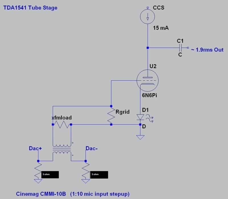
But I have these Cinemag 1:10 mic input stepup transformers. http://www.cinemag.biz/mic_input/CMMI-10BRevB.pdf With the TDA1541 being offset 2ma sink I would need to setup the TDA's for differential output (ie. 2 DAC's.) This way I can input the stepup transformer as in the schematic below below and cancel out the offset ( transformers like these can't stand any dc current on their windings.) I would even get some CMMR out of it. What I am finding the problem with this plan is no one seems to sell a PCB for balanced TDA1541 output, anyone know of one?
Last edited:
tried something like this some time ago for testing purposes, just without the output amp/buffer. The principle works.
Think you don't need a pcb to make this, the number of components is limited.
Think you don't need a pcb to make this, the number of components is limited.
Last edited:
- Status
- Not open for further replies.
- Home
- Source & Line
- Digital Line Level
- New look at tube analog for TDA1541