Hey guys, after a (very) long period of absence, I am returning to the wonders of DIY audio.
I had so many projects, I had to spent more than a year mastering my wood working skills just to get rid of most of the projects I wanted to build. Apart from speakers, I moved to furniture, completed an oak dinning table for 8 with Japanese joinery, a 4 set chair and table for a friends patio, even made a speaker out of concrete!
Unfortunately my crossover skills are still at 0, since I couldn't invest in measuring equipment. I give my projects to a local electrical guru, who is also a professor in a local technical university. He makes crossovers for most of my projects, hand wound coils, 2nd or 3rd order layouts, but I cant double check his work, since I have no measuring equipment.
For some time now I've been jumping over a set of JBL TLX 500 speakers friends and I blew some years ago at an X-Mas party. The speakers are 3-way, 8" woofer, 4-5" mid, and a tweeter. Both speakers are gutted and I've been wanting to replace the drivers and bring them back to life.
Here come the issues:
1) Speaker boxes are basically as is
2) No specs on the original drivers
3) OE X-over comprised of 2 coils, 3 caps and 2 resistors (strange for a 3 way)
4) New drivers will require a new X-over
I have basically selected replacement drivers, however will require help in coming up with a new crossover. I know I can just take them to the guy and let him do his work, but I want to do this myself.
Here's some tech specs:
- Boxes are 27 L volume, vented with ~6 cm diameter by 14.5 cm length
- Mid section comprised of a half sphere plastic chamber with volume of 0.5-0.8 L (4" OE driver)
Replacement drivers selected:
Low - Dayton DS 215 - 8 DS215-8 8" Designer Series Woofer Speaker 8 Ohm Specification Sheet
Mid - Dayton RS125 - 8 RS125-8 5" Reference Woofer 8 Ohm Specification Sheet
High - Dayton RS28F or Visaton G20SC or Visaton G25FFL
RS28F-4 1-1/8" Silk Dome Tweeter 4 Ohm Specification Sheet - RS28F
G 20 SC - 8 Ohm - G20SC
G 25 FFL - 8 Ohm - G25FFL
I've been experimenting with the Dayton combo in PCD, although I managed to come up with a reasonably flat response, phase tracking is all over the place. I use the provided FRD and ZMA files from Dayton, unfortunately no such data is available for the Visaton tweeters.
My layout is somewhat complicated, as I selected 3rd order for all drivers. I would like to stay above 5 ohms, however the RS28F is 4ohm and impedance falls under 5ohms at 3000 Hz. I suspect its not going to be a big issue, since there is little energy in the high frequency range but can't be sure. My component values look (at least to me) wierd, caps in the range of 50 to 100 uF with coils in the ranges of 0.1mH to 4.2mH. I don't know, I'm looking at the frequency response to be max flat.
I know 3-way X-overs are complicated for beginners, however I like to jump straight in the deep water. Any help and/or pointers will be much appreciated.
Update: I fiddled some more with PCD and came up with a 2nd order design for a proposed crossover layout. Will simplify construction and will bring the cost somewhat down.
I still don't know whether phase tracking is good or not and I cant seem to tame a small peak in the midrange. I would prefer to level the high section a bit more, but this might be due to the particular tweeter selection. Also, I don't know how important Zobel and LCR compensation networks are in a design like this. PCD suggests a 10mH coil in the LCR section for the midrange, which I think is overkill. Any thoughts?
I still don't know whether phase tracking is good or not and I cant seem to tame a small peak in the midrange. I would prefer to level the high section a bit more, but this might be due to the particular tweeter selection. Also, I don't know how important Zobel and LCR compensation networks are in a design like this. PCD suggests a 10mH coil in the LCR section for the midrange, which I think is overkill. Any thoughts?
Attachments
Did you introduce baffle step response to your drivers? Was PCD the only software that you used to simulate? Try to provide all the information in PCD so people can understand better what you have done with it. XSim is typically easier to use.
Unfortunately no, I still can't wrap my head around baffle step, and honestly tried to implement it a few times in PCD but to no avail. I have no other software apart from PCD for x-over design, but as stated in my 1st post - I am "toddler" in crossover design. 🙂
Will give Xsim a go as suggested, but really some of the advanced (for me) features such as Zobels, LCR comp. and baffle step puzzle me on how to implement them and their importance in some designs.
Will give Xsim a go as suggested, but really some of the advanced (for me) features such as Zobels, LCR comp. and baffle step puzzle me on how to implement them and their importance in some designs.
Probably the dayton woofer is not good for midrange, I mean the 5" which has an aluminum cone, and everybody know that metallic cones like to "ring".
A paper cone would be more "forgiving".
Keep the 5 " for future miniature speakers ( a 2"-2 "1/2 for a midrange if used in a 3 way system, and a miniature tweeter).
A paper cone would be more "forgiving".
Keep the 5 " for future miniature speakers ( a 2"-2 "1/2 for a midrange if used in a 3 way system, and a miniature tweeter).
Probably the dayton woofer is not good for midrange, I mean the 5" which has an aluminum cone, and everybody know that metallic cones like to "ring".
A paper cone would be more "forgiving".
Yes, I agree fully and am aware of this phenomenon. Let me just say that I still haven't bought the drivers. The reason for my selection is that the box is already flush trimmed for the OE drivers and I don't want to do additional work on the box itself, although will be required for the tweeter hole. I want to reuse all available box hardware, including the vent. I did measure the whole box from the inside and out, did 3D for reference and played with the volumes to match the tuning of the vent d and L.
The tricky part is the midrange, since it's closed volume chamber is a plastic half-sphere with a flange where the mid driver, chamber flange and box opening match the screw holes. The Dayton RS125 is the only driver that will fit my requirement as drop-in. Same goes for the woofer.
Going back to aluminum vs. paper, there is an RS125 P, although I was comparing the response data from the manufacturer, between 1kHz to 3kHz the aluminum seems to have a nicer curve (could be just me looking at a picture 🙂 ) including off-axis. That said, I've also read the the aluminum RS line requires more crossover work to compensate for ringing of the cone material and that they are not a first-timer's best friend when it comes to filter implementation.
Putting the speakers in the same enclosure is no good, despite of what everyone seems to do.
The speakers should be separate, and only the woofer needs some kind of backwave contention method ( if the room permits...)
An enclosure most of the time kills the sound, so it's better to start from the speakers alone.
A speaker could be super quality with 1 or 2 crossover components, who knows ?
The speakers should be separate, and only the woofer needs some kind of backwave contention method ( if the room permits...)
An enclosure most of the time kills the sound, so it's better to start from the speakers alone.
well, that's not strange...or you should start to complain about the quality of the chipboard, or the speaker's basket, or the tw assembly...3) OE X-over comprised of 2 coils, 3 caps and 2 resistors (strange for a 3 way)
A speaker could be super quality with 1 or 2 crossover components, who knows ?
Unfortunately no, I still can't wrap my head around baffle step, and honestly tried to implement it a few times in PCD but to no avail.
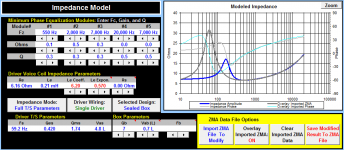
Gotta get yourself Response Modeler spreadsheet to generate baffle step curve that you will add to your Dayton graphs. In the Impedance model you can create zma files of your box and the small volume for the midrange. Import the zma files of your drivers in the impedance model and overlay it to the model created with TS parameters, then you can shape it with the tools ( minimum phase EQ modules, Le and Le expon.) until its inductive reactance part is exactly like the one from TS parameters except for the resonance peak, depending on particular case. Read the User Guide in the spreadsheet.
I'll post a .zma file as an example for your midrange.
The grey curve is Dayton zma of the driver measured free in air, and the blue one is modeled as shown. Now you'd only have to save it and your midrange impedance is pretty good for the sim.
Attachments
Last edited:
I did get my hands on Response Modeler, however I can't seem to make it work right. Its an Excel 2007 file, I'm running Win 10 with Office 2013 and its a mess. Clicking the buttons within the file brings back an error report then jumps and scrolls over the spreadsheet. Somehow I managed to get the ZMA files to load, adjust and then take them out, but PCD doesn't recognize the data in the ZMA file. I spent a few hours tackling this issues and I think I will have to manually copy all the ZMA data into a separate file and arrange it in 3 columns. According to Word, that's about 22 pages of raw numbers.😱 
In the mean time, also gave Xsim a go, nice little program if you know what you're doing. Me, I'm just clicking and playing with component values and looking like a kid in a candy store.
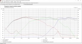
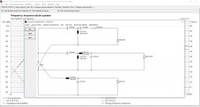
At this point I got really frustrated, having spent more than 2-3 hours and no results. I picked up a program that some here may have heard about, others maybe not. It's called Boxsim 1.20 and its available on the Visaton site. Basically their own software for their line of drivers, however it allows for T/S parameters and FRD and ZMA files to be imported. It doesn't allow you to do quick checks until ALL speaker data is entered. It calculates baffle dimensions, driver positioning, damping, box vol and type and provides for a passive or active filter.
So I did model the whole box as measured, with the Dayton combo, put in the FRDs and ZMAs and made it work. However, the resulting crossover is somewhat different from what PCD comes up with. Basically I plugged the numbers from PCD and there is a little nice extra called "crossover optimizer". Selected components can be optimized to meet certain criteria. Can't seem to export results in a meaningful format, so good 'ol print screen. 🙂
Any suggestions on how to fix Response Modeler? Please don't tell me I need to go back to Win 7 and Office 2007.
P.S. I switched the mid driver to the Dayton RS125 P -8. Note reversed polarity on mid and tweet. Tweet is 3rd order.
In the mean time, also gave Xsim a go, nice little program if you know what you're doing. Me, I'm just clicking and playing with component values and looking like a kid in a candy store.
At this point I got really frustrated, having spent more than 2-3 hours and no results. I picked up a program that some here may have heard about, others maybe not. It's called Boxsim 1.20 and its available on the Visaton site. Basically their own software for their line of drivers, however it allows for T/S parameters and FRD and ZMA files to be imported. It doesn't allow you to do quick checks until ALL speaker data is entered. It calculates baffle dimensions, driver positioning, damping, box vol and type and provides for a passive or active filter.
So I did model the whole box as measured, with the Dayton combo, put in the FRDs and ZMAs and made it work. However, the resulting crossover is somewhat different from what PCD comes up with. Basically I plugged the numbers from PCD and there is a little nice extra called "crossover optimizer". Selected components can be optimized to meet certain criteria. Can't seem to export results in a meaningful format, so good 'ol print screen. 🙂
Any suggestions on how to fix Response Modeler? Please don't tell me I need to go back to Win 7 and Office 2007.
P.S. I switched the mid driver to the Dayton RS125 P -8. Note reversed polarity on mid and tweet. Tweet is 3rd order.
Attachments
I am running prehistoric office and it works ok with RM and PCD, except Diffraction and Boundary Simulator. When I do actual design, it's easier for me to measure impedance and frequency response, then simulate in XSim or PCD. That way baffle step is covered to the fullest extent.
When I do actual design, it's easier for me to measure impedance and frequency response, then simulate in XSim or PCD.
How do you go about measuring a driver? Any particular method, hardware or software? I've set my aims at DATS v2 for a long time now, but my budget is preoccupied elsewhere. 🙂
This is turning quickly into a quest for gear if I am to do any meaningful work. I should also dig up my old laptop and make it a dedicated workstation to work with PCD, RM, etc. A lot of hassle for a replacement driver project, but should be worth it in the long run.
Measuring you can do with any software you fancy, people work with HOLMImpulse, REW, ARTA, there is lots of these. Take a look at a white paper How to Achieve Accurate In-Room Quasi-Anechoic Free-Field ...
- Status
- Not open for further replies.
- Home
- Loudspeakers
- Multi-Way
- New life for JBL TLX 500