
Not yet we are still working on it. It's a nightmare to track.
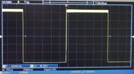
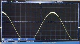
I can't tell from your photo of the sine-wave response if the waveform oscillates on the negative portion as well. Does it? Also, is the amp connected to a load? Do both boards behave in the same manner?
You mention (in your video) that you bought pre-stuffed boards. Do you know if their idle currents were set as a part of that? How does your experience compare to your friend's?
RTFM, hopefully you got at least a rudimentary one.
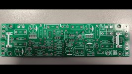
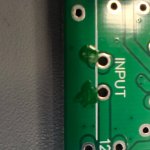
Eyeball those boards, maybe there are some missing compensation caps.
I'm sure it's disappointing to have this kind of problem, but it's likely that the folks who designed and sold the boards to you will try to make it right. It looks like you have some test gear so that can be helpful.
As an aside, when I was younger my Dad and I assembled quite a few Heathkit products. They were a lot of fun to build. Back then they weren't the only ones that offered kits -- I still have a kit-built 70W/ch tube amplifier that was sold by Allied Electronics. Haven't used it in decades but I couldn't bear to just get rid of it. Hey, some of the tube envelopes glowed blue when it was operating -- a built-in light show!
You mention (in your video) that you bought pre-stuffed boards. Do you know if their idle currents were set as a part of that? How does your experience compare to your friend's?
RTFM, hopefully you got at least a rudimentary one.
Eyeball those boards, maybe there are some missing compensation caps.
I'm sure it's disappointing to have this kind of problem, but it's likely that the folks who designed and sold the boards to you will try to make it right. It looks like you have some test gear so that can be helpful.
As an aside, when I was younger my Dad and I assembled quite a few Heathkit products. They were a lot of fun to build. Back then they weren't the only ones that offered kits -- I still have a kit-built 70W/ch tube amplifier that was sold by Allied Electronics. Haven't used it in decades but I couldn't bear to just get rid of it. Hey, some of the tube envelopes glowed blue when it was operating -- a built-in light show!
I've just ordered a MX50 and L20x2 from an ebay seller sow as reading the numerous threads on both Chinese amps. I bought kits so I can replaxce the semis with genuine parts from Mouser.
Similar osciillations were seen on them. One suggestion was to increase the quiescent current.
diyaudio.com/community/threads/power-amplifier-ljm-l20se.321025/page-7
It seems that some sellers have built theirs from a copied schematic which has deliberate errors.....
If you can find the schematic compare it with your boards.
If it is an LJM board, try asking member @ljm_ljm ljm_ljm@foxmail.com
The other cause may be fake components.
Last edited:
How didn't think of that before? LJM will be delighted to solve the problems with his boards, as usual.If it is an LJM board, try asking member @ljm_ljm ljm_ljm@foxmail.com
I bet he will come here to share schematics too...
<< SARCASTIC MODE OF>>
... and tell us to purchase just his impecable products.
And if you really want to build a fine amplifier, don't waste time and take this one. By using this board and genuine components I have attained 0.0015% THD at 10W and 0,005% at full power.
Last edited:
@Berlusconi, I see you are still a self opiniated hater of Ljm. Perhaps he's just not clever enough to make it work with fake components?
By the way, have you actually bought or constructed any of his designs?
Of course when I receive my MX50 and L20x2 i might have to agree but not until next year. I am replacing all transistors with Mouser sourced ones.
Toshiba's TTC0015b and TTA004b seem to be suitable drivers (160v) for the unobtainable 2SC5171 and 2SA1930, (if you exclude suspec t ones on ebay etc).
I don't see why the equally rare 2SD669a can't be replaced with a TTC015b.
Oh no @batteryman - strictly business. Hatred just clouds judgement and is unnecesarily emotionaly exausting. I just prefer to observe and talk if I find I can help others to avoid bad decisions. That's all.self opiniated hater
Yes, quite a few, and I have published test results here, at this forum. Most of them ended-up in trash. Meanwhile I went into my workshop to see if any is still there - just three boards have remained, the rest of them are now on scrapyard. Look at the snapshot below, these three remaining LJM boards besides my current system consisting entirely of DIY components (from the top to the bottom):By the way, have you actually bought or constructed any of his designs?
1. DAC based on Xingcore board
2. Preamp with 2-way Linkwitz-Rilley cross-over
3. Amplifier based on UPC2581V - for tweeters
4. LM3886 BTL Amplifier based on 12 chipamps in series/parallel configuration
All of these components are strictly Hi-Fi and I know that because I measure them.
Did you buy ready built LJM amps, or from kit, or from bare boards and bought the parts from reputable sources?
It would be useful to know what the fixes might be for these deficiencies in LJM amps rather than just dismissing them as trash.
You are implying that all the many other buyers of his amps have cloth ears as they seem happy with them, as did many posters on here.
I will build one of each using the supplied parts and the other two with Mouser parts so I can compare them and post my findings.
I would only buy kits after I know the schematic to avoid nonsense.
I would still be inclined to use semis from Mouser etc as there is simply no reliable way to tell the fakes.
I've just ordered them for both amps + 1000uf 10v Nichicon UKA caps.
The kits are cheap enough to justify a few $$s on new semis.
It will be interesting if my choice of substitutes works..LJM insists not to swap parts but that maybe because they are not available in China (export embargoes) so he can't say whether they would work.
Both, predominantly kits, because I want to measure components before soldering to avoid trivial faults. Kit components were predominantly fine - Chinese components aren't bad if not fake. I don't remember whether there was a single bad component in these kits. The problems can be connected with inadequate desin and quality control.Did you buy ready built LJM amps, or from kit, or from bare boards and bought the parts from reputable sources?
For example, these asymetric oscillations look like unimportant details but they hurt the very core of the amplifier: even though they look like small enough to be ignored, they may degrade the sound signifficantly. These oscillations affect small high frequency signals "riding" on large low frequency waves. It is important to realize that these high frequency detalis are the core of stereo illusion. Once the amplifier reproduces high power signals these oscillations destroy important high frequency information and sound becomes dull.
I agree those unwanted (parasitic?) oscillations are bad news and need to be fixed.
I don't know if the suggestions on the MX50 & L20 threads such as more quiescent current, reducing the gain, a few pf across the feedback resistor, small cap from B-E of the output transistoors (+ve rail side) etc worked. Did you experiment with these?
Here is the original L12 thread:
www.diyaudio.com/community/threads/l12-2-cfp-output-amp-120w-2-8r.196089/
Interestingly, the MX50, L20 and L12 all share common topolgy...... So any mistakes will be present on them all.
Also, there is a comment on the above thread about hf stability issues with the output stage.
Last edited:
OK, I review the schematic from https://www.diyaudio.com/community/threads/l12-2-cfp-output-amp-120w-2-8r.196089/post-3373053
The signal ground and the power ground are separated with R24. It expects your signal ground and power ground are shorted at another place somewhere in the system, usually at the power supply or at the metal case. If not, you should replace R24 with a wire. Try it to see if the issue is resolved.
It is often overlooked when you test it outside the metal case.
If they are not shorted, the input ground is bootstrapped by the feedback network, which is positive feedback. It might oscillate.
Are you sure?because they are not available in China (export embargoes)
Below is an expcert from Mouser invoice. Pay attention to COO:CN (Abbreviation for Country of origin: China)
Components are predoninantly from China, India, Thailand etc. And, by the way, money buys everything except love.
I meant LJM may not be able to import some of them.
Otherwise why does he & other sellers insist on using obsolete semis when newer alternatives exist? (apart from Chinese copies being the cheapest)
Otherwise why does he & other sellers insist on using obsolete semis when newer alternatives exist? (apart from Chinese copies being the cheapest)
Sure, newer alternatives exist because companies want to move forward, scrap everything and replace with "new" designs. Have you noticed that TI have abandoned almost all audio ICs and are offering many "new" and worse class-D amplifiers. They are at market to make money with new products. Quality comes at the 2nd place. Customers are sheep.Otherwise why does he & other sellers insist on using obsolete semis when newer alternatives exist? (apart from Chinese copies being the cheapest)
Before going into de circuit I need to say that I am a fan of LJM designs, I have a MX50SE and three L12-2 Ver 4, one of them working every day for a few years. This new L12-2 Ver 5 caught my attention righ away. As I am passionate about this topic, could not avoid the chalenge of finding how it works.
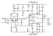
Now lets go to the circuit:
After examination it looks that the "Wart" is the current mirror of the input stage composed of two NPN BJTs (inside the box on schematic), this design seems to shares the input stage of the L20SE, the VAS has the traditional design with the 5551C (ECB) and the Miller compensation capacitor of 100 pF, the output stage is the CFP (Sziklai) configuration that is the brand image of the L12 design, this time with the drivers sharing more current.
New big difference to the old circuit is the two kind of capacitance multipliers in each rail feeding the input stage and VAS, perhaps a solution to improve stability on that area.
With simple simulation tests, and adjusting the voltage across the 0,1 ohm resistor to 5 mV, it shows a current on each power transistors arround 16 mA and 19 mA on the drivers. The current on the imput stage and VAS is 4 mA.
The solution of instaling the Vbias transistor to only one of the drivers to thermal coupling simplifies the circuit.
The current source circuit for the input stage and VAS shows a different aproach, usualy the cap (in this circuit a 33uF) negative pole goes inside two 10K resistors and this time is connected directly to the base of the transistors and only one 22 k resistor to ground, this design seems to have some oscilations during simulation.
To avoid reverse engineeing other tricks were used besides the "Wart", green glue strategically placed to avoid see trough and two dead ends on the circuit tracing.
Now I will solder all the components and do a "dyno" test on the bench, the results will come soon.
Everyone with additional information fell free to comment. Thanks
Attachments
From the video il looks like the L12-2 suffers from parasitic oscillation. A zobel filter on the output might get rid of it.
Looks like output stage oscillation that might be fixed by base stoppers like in the Self load invariant
- Home
- Amplifiers
- Solid State
- NEW L12/2 version 5. I have just received a pair of these amplifiers, I stopped testing because the boards are unstable