What is M-Noise?
Introduced by Meyer Sound, M-Noise is a new test signal that promotes standardized measurement of a loudspeaker system’s maximum linear output. It is a mathematically derived test signal that effectively emulates the dynamic characteristics of music.
Why M-Noise?
In any application requiring reproduction of musical content, M-Noise enables a far more accurate measurement of a loudspeaker system’s linear peak SPL than any other existing method.
M-Noise Download
M-Noise
Yep, it uses pink noise with a frequency dependent crest factor, where the crest factor increases as frequency increases.
It's supposed to replicate the crest factor in music better.
The purpose is to more accurately measure when non linear compression takes place.
If I remember correctly, Meyer recommends defining that point as where any two-octave band within the entire spectrum shows a 2dB decrease in level relative to low level response raised linearly.
imho, it's a test that would create great havoc for home hi-fi, particularly for low efficiency designs.
@ mark100
It does seem to offer something new, so worthwhile using it for tests. I expect that some vendors might have egg on their faces, if tests show unfavourable results 😀
One to watch 😉
It does seem to offer something new, so worthwhile using it for tests. I expect that some vendors might have egg on their faces, if tests show unfavourable results 😀
One to watch 😉
Very interesting and thanks for posting 🙂
As I understand its purpose, and painting with a very wide brush, for practical reasons we are usually tightly limited in the lower frequencies area, since speakers are large and expensive, we need large and expensive power amps, it´s hard to get reasonable efficiency, etc. , so we can´t happily overspec them, we are designing for "just what´s needed" and not much more.
While at the higher spectrum it´s the opposite: very high efficiency drivers, much less average power needed, so we can realistically "overdesign".
Power amp clipping is not even approached, hence we can get larger headroom and so a test signal with greater crest factor at higher frequencies is more realistic than plain pink noise.
It´s early morning here so I´m just listening to M-noise through $5 USB fed PC speakers, in principle it appears to sound like "smooth pink noise" with little to no rumble, no LF modulation (quite the opposite, it sounds very steady) while the high frequency component sounds grainy/broken.
Not sure it´s my signal chain breaking up and clipping HF peaks or it´s in the nature of the beast.
Later I´ll formaly wake up and test it with a real amp and speakers.
Thanks again.
Later I´ll formaly wake up and test it with a real amp and speakers.
Thanks again.
Did it break something? I might wait a little ☺
@ mark100
It does seem to offer something new, so worthwhile using it for tests. I expect that some vendors might have egg on their faces, if tests show unfavourable results 😀
One to watch 😉
Zero D, seems like something new to me too.
I know in the prosound world that maximum sustainable SPL is always a system design specification/objective.
And that the max SPL spec has typically been about the onset of thermal compression.
Most tests run sine sweeps at increasing voltages until compression is apparent somewhere in the spectrum. (I know you're probably familiar with this...I'm just saying it for any following along who might not be...)
Anyway, the point I'm trying to make is that max SPL is generally measured/defined from an RMS point of view...probably with more emphasis on the low end of the frequency range where drivers draw more current.
I think what's different about M-Noise, and greatly needed, is that M-Noise seems to be a test that is more about sustained peak capability....and probably focused on the high end of the frequency spectrum because of its increased crest factor there.
Most pink noise generators I've seen use a crest factor of around 12dB, rms to peak. I'm guessing M-Noise gets to at least an 18dB crest factor.
That equals needing 64 x rms wattage, for uncompressed peaks!!
Like I speculated earlier, I'm guessing this is a huge source of transient constraint, with most of home hi-fi.
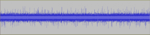
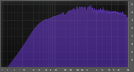
Extra thanks added for these graphs, VERY useful.
The first one shows me that the "crackling added to plain pink noise" I heard is actually there, those WAY louder than average peaks.
I am not into Hi Fi or PA but Musical Instrument amplification, the frequency distribution shown will be very useful to me on 2 counts:
1) the bass rolloff somewhat mimics MI output.
2) the increased HF peaks do not exist in Rock Guitar sound, which typically roll down 24dB/oct above some 3 kHz, but are *great* to test extended range Bass Guitar cabinets, when used by Slappers.
Which are a great part of my customers ... so much so that my Bass preamps include a "Slap" button, go figure.
Tweeters are normally protected by series lamp bulbs ... which by definition *force* Power Compression which this signal will bring out.
I bet this signal will let me optimize crossovers and protection.
Thanks again. 🙂
Last edited:
Actually, the spectrum is flat down low.@ JMFahey
Hope you find it useful, & let us know your test results
@ mark100
Here's a couple of screenshots
Just yesterday I downloaded the .wav and used it as output from Clio.
I´ll test some speakers next week but the 17,5dB CF makes me a bit scared - my test amps are either an UcD180 (40Vp) or an UcD2k (140Vp😬).
- Home
- Loudspeakers
- Multi-Way
- New free test signal from Meyer Sound