Hello There:
Just picked up these organ-pulled mono amps from the early sixties. I will be using them (if they work) as an interim amp in my stereo while I do some repair and upgrade work on my main amp. If they sound good I will replace both chassis and put them on nice walnut bases, while upgrading wiring, connectors, and any and all components not worth keeping. All superfluous devices, openings, connectors etc. will be eliminated.
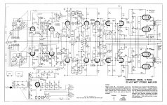
Although these are apparently quite common around here (made in Canada by Electrohome for the US Kinsman organ company), I have had troubles finding a schematic. I have posted one image of a likely possibility. I don't have these in my hands yet so I will post more pictures later when this becomes possible. Pretty sure most of the music related circuitry is already gone - hence the empty tube positions.
The seller tells me these sound great and are fully functional. The current tube complement is 2x7189 (or EL84), 1x6GH8A, rectifier 5V4.
I am posting this with some pics for a bit of basic info, input, or suggestions. I am curious to know what circuit this likely is based on. Does anyone recognize those OPTs? Are they likely worth keeping? Is it possible that one 6GH8A is occupying the spot that a 12AX7 once did before this was converted from an organ amp to an audio monoblock?
Link to photos
Let me know your thoughts!
Thank for any and all suggestions!
Best regards,
David
Just picked up these organ-pulled mono amps from the early sixties. I will be using them (if they work) as an interim amp in my stereo while I do some repair and upgrade work on my main amp. If they sound good I will replace both chassis and put them on nice walnut bases, while upgrading wiring, connectors, and any and all components not worth keeping. All superfluous devices, openings, connectors etc. will be eliminated.
Although these are apparently quite common around here (made in Canada by Electrohome for the US Kinsman organ company), I have had troubles finding a schematic. I have posted one image of a likely possibility. I don't have these in my hands yet so I will post more pictures later when this becomes possible. Pretty sure most of the music related circuitry is already gone - hence the empty tube positions.
The seller tells me these sound great and are fully functional. The current tube complement is 2x7189 (or EL84), 1x6GH8A, rectifier 5V4.
I am posting this with some pics for a bit of basic info, input, or suggestions. I am curious to know what circuit this likely is based on. Does anyone recognize those OPTs? Are they likely worth keeping? Is it possible that one 6GH8A is occupying the spot that a 12AX7 once did before this was converted from an organ amp to an audio monoblock?
Link to photos
Let me know your thoughts!
Thank for any and all suggestions!
Best regards,
David
Last edited:
With a little re-designing, they could provide sweet service as audio amps.
Particularly since they've got decent UL outputs.
Some of that "extra" stuff can be torn out if used as power monoblocks.
Such as everything before the main amp's input jacks, and the vibrato/regulator stuff.
Perhaps beef up a bit on the PS design, but no need to go wild.
Particularly since they've got decent UL outputs.
Some of that "extra" stuff can be torn out if used as power monoblocks.
Such as everything before the main amp's input jacks, and the vibrato/regulator stuff.
Perhaps beef up a bit on the PS design, but no need to go wild.
I would do the least possible on them to get where you want to go.
The OPT and PTX both look well-sized for the service. Build a pair of nice bases for those chassis to sit in, repurpose the empty sockets (magic-eye VU meters perhaps?), optimise the output for full audio range and enjoy. That way you keep the history and patina while making them fit for purpose.
Anyway, thats what I would do. They are yours so you do what you wish! I'm jealous. Have fun.
The B+ PSU is easily "goosed up" by using Sovtek 5AR4s, with the series SS diode tweak, instead of 5V4s. Heating current for the 2 types is the same at 2 A. However, the 5AR4 exhibits a smaller forward drop and is more tolerant of a decent sized 1st filter capacitor. 🙂 UF4007s, instead of the 1N4007s shown, are inherently quieter, but the vacuum rectifier will block SS diode switching noise from entering the B+ rail. Given my "anal retentive" mindset, I worry about noise sneaking into the power trafo. Less noise, from the outset, can't be bad. If at all possible, make the B+ filter CLC. The affordable Triad C-14X is rated for 200 mA. and the 5V4 is rated for 175 mA.
The Russian 6Π14Π-EB (6n14p-ev), AKA EL84M, is a nice, true, 7189 equivalent. The 6Π14Π-EB exhibits decent sonics and is "tougher than old rubber boots".
Modeling the power section of the Sherwood S5000 is (IMO) a good idea. The 6GH8s you already have, along with the 6BL8 and 6U8, substitute satisfactorily for the made of "unobtainium" 7199 shown in the schematic.
Attachments

Hello:
Thank you all for the input. I am relieved to see no major concerns - perhaps this was not a stupid move after all!
I used to think the EL84 was a desirable power tube until I bought these museum pieces and read about the 7189. Now that I have read about the 6N14N-EB, that is where I am inclined to go. I used some military grade Russian 6N1P in my preamp as replacement for 12AU7A. I had to re-wire the filaments as it was not a drop-in. But the improvement was instantly noticeable, even though I was replacing some nice clea-rtop RCA tubes. I am a fan of these Russian tubes, especially given the price and apparently rugged build.
I am eager to see what kind of biasing arrangement these amps have. The reason my ST70 is headed for the bench is that it lacks the test-points on the front for reading bias during adjustment. The operation is an ordeal as I need to turn the amp over to install four alligator clip test leads. It is a major, hazardous venture and therefore I almost never check the bias, even when I want to.
As for rectifiers - thank you for the suggestion. I will give that some serious thought. I do very much like the fully SS option. I use one of these in the ST70, and I am very happy with it. Drop in, forget, don't worry about the next light show.
The suggestion of maintaining the original patina is appealing too, thank you. But those boxes are very long and full of unused openings (at least four huge ones, not to mention the 5 extra RCA positions and myriad of screw holes). Aesthetic considerations are huge for me as I have learned that attention to detail and compact footprint in this arena is crucial to spousal acceptance of any new gizmo in our living space.
Anyway before I do too much planning, I will need to assess them and see if the rebuild is worth the bother. Will post some pictures next week when I get my hands on them.
Thanks again!
David
One can always buy a nice Hammond chassis of an appropriate size, and transfer the transformers, install new tube sockets, and configure as needed, if concerned with appearance.
Agreed. For now I am leaning that way.
Any thoughts on what is preferable, steel or aluminum? I am sure steel presents a better barrier to EMI, but can that even contribute to a more quiet final result? Working with hand tools, the advantages of aluminum are compelling...
Hammond offers both.
Any thoughts on what is preferable, steel or aluminum? I am sure steel presents a better barrier to EMI, but can that even contribute to a more quiet final result? Working with hand tools, the advantages of aluminum are compelling...
Hammond offers both.
Aluminum doesn’t conduct magnetic flux, so it’s preferable. I can confirm the 6P14P-EV are excellent for the money and are extremely robust. Try the “K” variant. Not as robust but more musical. However, you cannot go wrong with either. I prefer these Russian variants of the type to many premium NOS tubes.
Personally, I like the easier construction using aluminum chassis.
Never had an issue, I pre-design layout on paper, use sensible locating of components, and consider wiring arrangements/lead dress for no issues later on.
Tube socket orientation is important too, pin orientation helps eliminate excess wiring.
Never had an issue, I pre-design layout on paper, use sensible locating of components, and consider wiring arrangements/lead dress for no issues later on.
Tube socket orientation is important too, pin orientation helps eliminate excess wiring.
Hello all:
Quick update for you...
Still have not received my amps yet so no new pictures for a while.
I have been reading up on circuit etc. A big thanks to Eli Duttman. I will definitely by basing this amp on a stripped down half of the Sherwood S-5000. Also intend to use the Russian 6N14N-EV.
I am trying to sort out a few technical issues:
1. I would like to have individual bias trim pots on the output tubes. Are there any pitfalls going this route?
2. Also the pentode triode 6GH8 bases phase splitter... Is this worth keeping. Seems like a great replacement for the 7199 but I have not read anywhere that this is a great performer. Should I be looking at a different phase splitter all together?
Again - thanks for any and all suggestions...
Best regards,
David
Individual bias trim pots. for each of the 4X O/P tubes offers maximum flexibility.
MANY a Dyna ST-70 has been reworked to use the 6GH8 as a "replacement" for the extraordinarily difficult to source 7199. People are happy. 😉
MANY a Dyna ST-70 has been reworked to use the 6GH8 as a "replacement" for the extraordinarily difficult to source 7199. People are happy. 😉
Update!
The amps have arrived safely. I will post pictures shortly. They appear to be unmodified, original organ amps. There are two 6HG8 drivers and two EL84's, plus a bunch of other organ effects and tone related 12AX7s. There is one big leaking cap inside, so I won't even bother to power these up. I will just disassemble them, and retain what I will use (all the iron and the tube sockets are good too). Chassis are way too big.
Definitely I will be using a half of the Sherwood 20+20, configured with one 6HG8 driver∕phase splitter. I have a couple things I need to solve however. Hoping the folks here might be able to share some insight with this Sherwood S5000 circuit...
In the attached mark-up I have outlined the amp section, or the circuit I will be creating for each monoblock:
Sign in to your account
If I don't want the Damping Factor control, is it correct to delete the wire shown in blue, and eliminate the 0.47 Ohm resistor R73 at the driver pentode cathode?
Is it possible the 1W resistor R58, 12 Ohm is a typo in this diagram? It seems odd that a 12 Ohm value follows the 47 kOhm (R60∕R63) and fraction of the 15 kOhm trim pot (R61) in series... Seems like this would be more likely 12 kOhm, and not 12 Ohm.
Also the notes at the bottom concerning the capacitor values are a bit confusing. It says '* Match within 3%... ... All fractional valued capacitors are in uF and are 400V, molded paper; other capacitors, except electrolytics are in XXX and are mica or ceramic' (can't read the XXX, looks like uuF, which makes no sense). Also every cap on the schematic uses the symbol normally applied to electrolytics - so I am left wondering which should be electrolytics and which ones should be ceramic∕film∕mica etc.
Thank you everyone, as usual - any input is much appreciated!
Best regards,
David
Last edited:
can't read the XXX, looks like uuF, which makes no sense
That XXX is μμF., which is how pF. used to be expressed.
Get rid of the center channel stuff. That's obvious in a monoblock.
Last edited:
That XXX is μμF., which is how pF. used to be expressed.
Get rid of the center channel stuff. That's obvious in a monoblock.
Thank you.
Not sure what you mean by center channel stuff. Anyway, at the link below is what I am planning. Added triode-ultralinear switches. Next revision I will change the balance pot for individual fixed bias trim pots...
Sign in to your account
Best,
D
Hi Again:
Here are some pictures. These things are really big. I think I will be able to get them to fit on an 8 x 10 in. (or thereabouts) chassis.
Sign in to your account
Here is the circuit, with individual bias pots on each output tube, and the ultralinear-triode switches:
Sign in to your account
Would there be any problem using the ultralinear-triode switches in this circuit?
Best regards,
David
Last edited:
- Home
- Amplifiers
- Tubes / Valves
- New EL84/7189 Monoblock Project