Things are finally slowing down at work, to an extent, so I thought I'd take some time to make another waveguide. I'm in the habit of naming them after Intel CPU architectures, so this one's called "Nehalem."
It measures 250mm in height and 280mm in width (about 10" x 11") and should be printable in one pass using a Creality Ender 3 or something comparable.


The waveguide itself is fairly straightforward oblate spheroidal, for the most part. Something that I like to do with my waveguides, is design them so that they're inserted into a sonotube. I do this for a few reasons:
1) By putting them in a Sonotube, you get a huge ol' roundover, and roundovers tend to smooth out the overall response of a waveguide. You can make a roundover using PVC pipe, but I don't like cutting PVC pipe. You can make a roundover with your 3D printer but that eats up precious space on the print bed. I think that roundovers make speakers "disappear" better too. It always amazed me how the giant Gedlee Summas sounded much smaller than their actual size. (Summas used a 2.25" radius roundover on all sides.)
2) One not-so-obvious benefit of putting a waveguide in a Sonotube is that you can use a much narrower vertical angle while still keeping mouth size under control. Basically, because the left and right edges of the waveguide are shorter (because it's a cylinder) it limits the horizontal width of the waveguide.
The waveguide is designed for the 16mm BMS 4526HE-8 or 16. It should work fine with the 4526 too I think (I don't have the 'regular' version.)
Vertical coverage is approximately 93 degrees and horizontal coverage is 120 degrees.
It measures 250mm in height and 280mm in width (about 10" x 11") and should be printable in one pass using a Creality Ender 3 or something comparable.
The waveguide itself is fairly straightforward oblate spheroidal, for the most part. Something that I like to do with my waveguides, is design them so that they're inserted into a sonotube. I do this for a few reasons:
1) By putting them in a Sonotube, you get a huge ol' roundover, and roundovers tend to smooth out the overall response of a waveguide. You can make a roundover using PVC pipe, but I don't like cutting PVC pipe. You can make a roundover with your 3D printer but that eats up precious space on the print bed. I think that roundovers make speakers "disappear" better too. It always amazed me how the giant Gedlee Summas sounded much smaller than their actual size. (Summas used a 2.25" radius roundover on all sides.)
2) One not-so-obvious benefit of putting a waveguide in a Sonotube is that you can use a much narrower vertical angle while still keeping mouth size under control. Basically, because the left and right edges of the waveguide are shorter (because it's a cylinder) it limits the horizontal width of the waveguide.
The waveguide is designed for the 16mm BMS 4526HE-8 or 16. It should work fine with the 4526 too I think (I don't have the 'regular' version.)
Vertical coverage is approximately 93 degrees and horizontal coverage is 120 degrees.
Attachments

I'm from the Seattle area, and something that I took for granted, living there, is that the DIY audio community is really active there. Where I live now? Not so much.
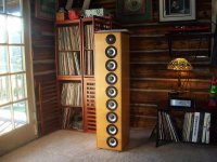
Over 21 years ago I went to the "Vacuum State of the Art" conference in 2001, and one of the speakers that grabbed my attention was The Bottlehead Straight 8 speaker.
The speaker clearly had some issues; the highs didn't really blend in. But I was impressed by how dynamic the Straight 8s were.
This "Nehalem" speaker that I'm working on is going to take a few cues from The Straight 8s, but I also intend to address what I consider their "Achilles heel." (The lack of integration between the tweeter and everything else.
Lynn Olson has an account of the show here: https://web.archive.org/web/20030812035157/http://www.aloha-audio.com/VSAC2001.html
I vaguely recall meeting John Sheerin there as well, I believe he built one of the horn speakers that were demonstrated.
Attachments

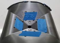
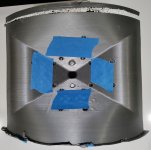
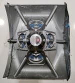
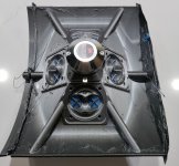
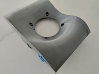
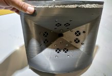
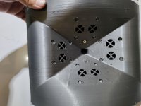
In order to make this thing work, it's going to be a woofer-woofer-midrange-tweeter-midrnage-woofer-woofer (WWMTMWW)
There will be a Unity horn in the center with four Dayton ND64-16s wired in parallel for a 4ohm load
The woofers are the same as the Bottlehead Straight 8, the MCM 55-1870
For now, I'm only using four woofers. I can increase the array length to six or even eight elements. But at the moment, I'm going with four. That offers about as much displacement as a ten inch woofer.
In a bit of a twist, the speaker is currently designed as a cardioid for the woofers, a dipole for the mids and a monopole for the tweeter
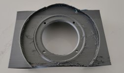
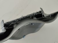
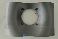
Attached are some pics of the woofer baffles. This particular one failed 80% of the way through, that's why it's open at the top
There will be a Unity horn in the center with four Dayton ND64-16s wired in parallel for a 4ohm load
The woofers are the same as the Bottlehead Straight 8, the MCM 55-1870
For now, I'm only using four woofers. I can increase the array length to six or even eight elements. But at the moment, I'm going with four. That offers about as much displacement as a ten inch woofer.
In a bit of a twist, the speaker is currently designed as a cardioid for the woofers, a dipole for the mids and a monopole for the tweeter
Attached are some pics of the woofer baffles. This particular one failed 80% of the way through, that's why it's open at the top
Attachments

Hi Patrick/John,
Kindest regards,
M
Could you describe, how you create/draw the rounded front face? I have an enclosure that is made from a Sonotube-like concrete form, and it would be nice to have the same radius curve on the wave-guide to blend the two together.Something that I like to do with my waveguides, is design them so that they're inserted into a sonotube. I do this for a few reasons:
Kindest regards,
M
Yeah I can probably write that up over the weekend.
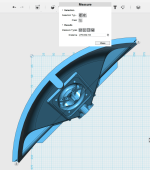
There's the easy way:
You draw an arc in 2D. You extrude the arc. Then you make a waveguide and merge it with the solid you made with the arc.
That's the easy way, but it's not "perfect." If you want the mouth to be perfectly square, you have to draw a profile of the waveguide, and then rotate that profile along a line that goes right through the center of the cylinder. This produces a better looking waveguide, one with a mouth that's perfectly square, but it's challenging to model.
The waveguide in this thread uses the "easy way." This waveguide from Grimaldi Systems uses the "hard way:"
I immediately think of the Jamo Oriel from the 90's when I look at the shape of the waveguide View attachment 1156457
These are wild, I've never seen them before. Reminds me a bit of the Kef speakers from the late 80s and early 90s that used a two-way for the midrange and tweeter, along with woofers in a bandpass enclosure.
I had a heck of a scare tonight!
I've 3D printed the waveguide for one speaker. I've installed all the midranges. I've measured the tweeter. I've 3D printed four woofer enclosures.
IE: this project is pretty far along.
I've become a bit of an expert at bending the rules, when it comes to using midranges in a Unity horn. Theoretically, these Dayton ND64s shouldn't work. Their QES is too high.
But I've been doing this for so long, I've figured out some tricks to make mids work which wouldn't normally work. In particular, with larger midranges (five inches or larger) you run into an issue where the pathlength difference between the edge of the midrange cone and the center of the midrange cone can limit how high your mids play. For instance, in a 5" midrange like what's used in the Danley SH-50, the edge of the cone is about two inches out of phase with the middle of the cone. 6500Hz is two inches long. This means that you wind up with a null at about 3250Hz that's caused because the sound radiated by the edge is one half wavelength out of phase from the center of the midrange.

In this measurement of Scott Hinson's Synergy Horns, from https://www.diyaudio.com/community/threads/synergy-horns-dayton-and-prv.244890/page-5 you can see the null at 3250Hz. (There's other nulls too, 3250hz is just one of them.)
Long story short: when you're using midranges with a diameter of just two inches, and you design the phase plug carefully, you can sometimes push the midranges higher than you might expect.
Or at least that was my hope.
This evening I measured my midranges, and they played all the way up to 4000hz... But the distortion was just OFF THE CHARTS.
I didn't even bother to save the measurement.
My first assumption was that I had a broken midrange, I'd damaged one, or both. Lately I've been using a propane torch to solder, so my 'gut' reaction was that I must have trashed a midrange accidentally while soldering.
So I took all the mids apart... and everything looked fine.
You guys have probably noticed that I never finish projects. And when my midranges were distorting like crazy, I came THIS close to throwing in the towel. It doesn't take very much to convince me to start all over again, which is why I've published 100+ projects but none of them ever get finished. It's just really really easy to convince me to toss projects in the trash and try again.
But since I've easily invested 40-60 hours already, that seemed excessive.
I took out every single midrange, and doubled the thickness of the gasket. (I'm using mortite as a gasket for the midranges.)
By that point, it was too late to measure the speakers again. So I just hooked them up to my amplifier and played some music.
Once again, it was distorting like crazy.
This was a HUGE bummer. The drivers looked fine, I'd double the thickness of the gasket, checked all the wiring... Everything looked fine.
Finally, I got out a flashlight and tried to observe the displacement of the midranges. Perhaps they were running out of xmax? But they looked fine.
Then I FINALLY saw the problem: a single nut was stuck to the voice coil of a single midrange. Basically a nut had slipped into the gap between the spider of the midrange, and the magnet. I'm using very small nuts and bolts for the mids, and one had weaseled it's way into the gap. So every time one of the midranges moved, it was making that nut buzz. I removed the nut and now it sounds perfectly fine.
FINALLY.
I've 3D printed the waveguide for one speaker. I've installed all the midranges. I've measured the tweeter. I've 3D printed four woofer enclosures.
IE: this project is pretty far along.
I've become a bit of an expert at bending the rules, when it comes to using midranges in a Unity horn. Theoretically, these Dayton ND64s shouldn't work. Their QES is too high.
But I've been doing this for so long, I've figured out some tricks to make mids work which wouldn't normally work. In particular, with larger midranges (five inches or larger) you run into an issue where the pathlength difference between the edge of the midrange cone and the center of the midrange cone can limit how high your mids play. For instance, in a 5" midrange like what's used in the Danley SH-50, the edge of the cone is about two inches out of phase with the middle of the cone. 6500Hz is two inches long. This means that you wind up with a null at about 3250Hz that's caused because the sound radiated by the edge is one half wavelength out of phase from the center of the midrange.
In this measurement of Scott Hinson's Synergy Horns, from https://www.diyaudio.com/community/threads/synergy-horns-dayton-and-prv.244890/page-5 you can see the null at 3250Hz. (There's other nulls too, 3250hz is just one of them.)
Long story short: when you're using midranges with a diameter of just two inches, and you design the phase plug carefully, you can sometimes push the midranges higher than you might expect.
Or at least that was my hope.
This evening I measured my midranges, and they played all the way up to 4000hz... But the distortion was just OFF THE CHARTS.
I didn't even bother to save the measurement.
My first assumption was that I had a broken midrange, I'd damaged one, or both. Lately I've been using a propane torch to solder, so my 'gut' reaction was that I must have trashed a midrange accidentally while soldering.
So I took all the mids apart... and everything looked fine.
You guys have probably noticed that I never finish projects. And when my midranges were distorting like crazy, I came THIS close to throwing in the towel. It doesn't take very much to convince me to start all over again, which is why I've published 100+ projects but none of them ever get finished. It's just really really easy to convince me to toss projects in the trash and try again.
But since I've easily invested 40-60 hours already, that seemed excessive.
I took out every single midrange, and doubled the thickness of the gasket. (I'm using mortite as a gasket for the midranges.)
By that point, it was too late to measure the speakers again. So I just hooked them up to my amplifier and played some music.
Once again, it was distorting like crazy.
This was a HUGE bummer. The drivers looked fine, I'd double the thickness of the gasket, checked all the wiring... Everything looked fine.
Finally, I got out a flashlight and tried to observe the displacement of the midranges. Perhaps they were running out of xmax? But they looked fine.
Then I FINALLY saw the problem: a single nut was stuck to the voice coil of a single midrange. Basically a nut had slipped into the gap between the spider of the midrange, and the magnet. I'm using very small nuts and bolts for the mids, and one had weaseled it's way into the gap. So every time one of the midranges moved, it was making that nut buzz. I removed the nut and now it sounds perfectly fine.
FINALLY.
Attachments


Hi Patrick/John,
I try the second way as, based on your description it appears more manageable.
Kindest regards,
M
P.S. I am glad that you found the problem.
M
Thank you for the hints. I was actually trying "the easy way", which proved not that easy, probably due to being still quite a beginner with the 3D software.Yeah I can probably write that up over the weekend.
I try the second way as, based on your description it appears more manageable.
Kindest regards,
M
P.S. I am glad that you found the problem.
M
What is the radies of the "Waveguide/Unity horn.
The Orion is not a tube ,bur an oval
Bernt Båndsei
The Orion is not a tube ,bur an oval
Bernt Båndsei
What is the radies of the "Waveguide/Unity horn.
The Orion is not a tube ,bur an oval
Bernt Båndsei
This waveguide is designed to be integrated into a sonotube with a diameter of 16" / 406.4mm
You can use a sonotube with an internal diameter of 12" / 304.8mm
The reason you can do this is because the waveguide comprises 25% of the circumference of a cylinder with a diameter of 16":
1) the circumference of a 12 inch sonotube = 2 * 3.14159 * 6" = 37.7"
2) the circumference of a 16 inch sonotube = 2 * 3.14159 * 8" = 50.27"
3) 75% of the circumference of a 16 inch sonotube = 0.75 * 2 * 3.14159 * 8 = 37.7"
Therefore: a twelve inch sonotube can be used for a tube that's 16" in diameter if you replace 25% of the circumference with a waveguide that's comprises 25% of the tubes circumference... which is what I've done in this project.
Obviously this same concept applies to any shape, not just waveguides. If you're trying to make a sonotube subwoofer with a diameter of 16 inches, you can use a 12 inch sonotube if you replace 25% of the sixteen inch sonotube with something 3D printed, like a subwoofer port.
Attachments
Attached is the following:
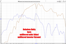
1) The measured response of the BMS 4526HE-8 on the "Nehalmem" waveguide with no filters
2) The measured response of 4 x Dayton ND64-16 on the "Nehalem" waveguide with no filters (yes, the tweeter really is 14dB more efficient!)
3) The FRD and ZMA files for both
1) The measured response of the BMS 4526HE-8 on the "Nehalmem" waveguide with no filters
2) The measured response of 4 x Dayton ND64-16 on the "Nehalem" waveguide with no filters (yes, the tweeter really is 14dB more efficient!)
3) The FRD and ZMA files for both
Attachments
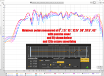
Here's the polar response of the Unity horn in this "Nehalem" speaker.
This is using my first attempt at a passive xover for this speaker.
"Nehalem" is going to be a hybrid:
1) the crossover is passive
2) But the speaker requires EQ to play flat
Basically the idea here, is that I'd prefer a passive speaker because I don't want to deal with the hassle of using a bunch of amplifier channels and I generally find that active speakers tend to be noisy.
So the passive crossover gets us "in the ballpark" but the speaker needs EQ to play flat.


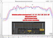
Here's the response with 6th octave smoothing and 12th octave smoothing. There some peaks and dips in the unequalized response, but once it's equalized it sounds pretty good to me. I think I need to cut the midrange a little about, about 2dB, to take it to the next level.
I haven't added woofers into the mix yet, hopefully I can wire those up tomorrow.
Like all good Unity horns, the midranges and tweeters basically behave like a single full range speaker.
This is using my first attempt at a passive xover for this speaker.
"Nehalem" is going to be a hybrid:
1) the crossover is passive
2) But the speaker requires EQ to play flat
Basically the idea here, is that I'd prefer a passive speaker because I don't want to deal with the hassle of using a bunch of amplifier channels and I generally find that active speakers tend to be noisy.
So the passive crossover gets us "in the ballpark" but the speaker needs EQ to play flat.
Here's the response with 6th octave smoothing and 12th octave smoothing. There some peaks and dips in the unequalized response, but once it's equalized it sounds pretty good to me. I think I need to cut the midrange a little about, about 2dB, to take it to the next level.
I haven't added woofers into the mix yet, hopefully I can wire those up tomorrow.
Like all good Unity horns, the midranges and tweeters basically behave like a single full range speaker.
Attachments
Last edited:
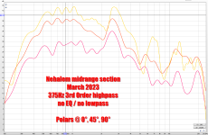
In the measurements from 0 to 45 degrees, it's not 100% clear that there's a lot of rejection off-axis. For instance, at 45 degrees off axis, the output is "only" down 3-4dB:
But at 90 degrees off axis, the output is down about 8-10dB:

The graph above shows output on axis, 45 degrees off axis, and 90 degrees off axis.
But at 90 degrees off axis, the output is down about 8-10dB:
The graph above shows output on axis, 45 degrees off axis, and 90 degrees off axis.
Attachments
- Home
- Loudspeakers
- Multi-Way
- Nehalem