L.S.
I'm putting together a new amp with old iron. The power xformer has a center tap, but the xformer in the original schematic doesn't.
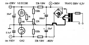
No problem for the HT, but I'm not so familiar with negative supplies, especially how it's done here:
So my question is: how do I adapt this to a CT transformer? 😕
Thanks!
I'm putting together a new amp with old iron. The power xformer has a center tap, but the xformer in the original schematic doesn't.
No problem for the HT, but I'm not so familiar with negative supplies, especially how it's done here:
An externally hosted image should be here but it was not working when we last tested it.
So my question is: how do I adapt this to a CT transformer? 😕
Thanks!
It's usually the SS forums I frequent but no matter. What's the secondary voltages of the new CT tranny ? It would need to be a 300-0-300 to use the CT as the ground. The CT would go to ground, (Your bridge is shown reversed by the way). So CT to ground, positive output from bridge to +400v and negative side of bridge to -400v The two diodes and 22uf are ommited. Diodes in the bridge drawn reversed 🙂
Also you don't need adapt... if the secondary voltage is correct you can ignore the CT. So if it's 150-0-150 just ignore the CT.
Also you don't need adapt... if the secondary voltage is correct you can ignore the CT. So if it's 150-0-150 just ignore the CT.
Attachments
Assuming the centre-tap will be grounded, it is actually simpler. You know how to build a positive supply from a CT transformer with two diodes. Just do the same thing for a negative supply, with the diodes reversed. The four diodes can be combined in a bridge, but the wiring will be different from that shown above.
- Status
- Not open for further replies.