I have a Sansui AU-9500 that I’ve done some work on. I replaced all of the electrolytics, relay, bias and offset trimmers, and replaced all of the 2SA726 and 2SC1313s with KSA992 and KSC1845s.
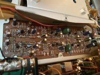
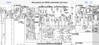
There is a VERY intermittent issue in the right channel where it all of a sudden gets a lot of crackles and pops and it can get kind of loud and then go away for a little while until it comes back again. It’s very annoying. By swapping the preout/main in cables I found the issue was in the preamp section. The popping is not affected by the volume control, that and by swapping the input wires on the tone board has gotten the issue isolated to the tone control board itself. Looking at the schematic the only thing between the volume pot and the preout is the tone control. I’ve tried using freeze spray to isolate the issue with no success. The issue really seems like a transistor issue and the only four transistors on the board that weren’t replaced were a pair of 2SC1364 and a pair of 2SK30A. I replaced the 2SC1364 with a pair of KSA1815. After that I thought I had repaired it as it was issue free for over a full day of playback.
Unfortunately it’s making the noise again. It doesn’t make the noise long enough to use a scope to try to find it. The only other transistors on the board is the 2SK30A. One was replaced in the past and it happens to be in the right channel, the channel with the issue. It was replaced with a GE FET-1.
I happen to have some 2SK170s on hand. I haven’t done a lot of matching fets, not as much and your regular transistors that is, but it seems to be over qualified for the job. Would the 2SK170 make a decent replacement?
There is a filter switch board that interacts with the tone board, but it just has resistors, polyester caps and the switches which were cleaned. The noise doesn’t go away when I flip the switches.
Any other ideas on what the issue could be?with it being so intermittent is making this a nightmare.
PS, thought I should add that I held my iron to the fet in the right channel and it didn’t seem to make it faulty, but not sure if that means anything since freeze spray isn’t able to eliminate the issue.
Dan
Attachments
Last edited:
The 2SK30A(Y) is at a low current setting (Rs=9.2k, Rd=10k), so a 2SK170 is forced to a low current setting too. But the final setpoint of TR703 can differ, depending on the difference of the Vpo's of the jfet's. You can try it, but have it a burn in without an input signal (to avoid clipping due to this changed setpoint of 703) to see if the crakles are gone.
What's the railvoltage? That's needed to calculate the right value of R711 for applying a 170.
What's the railvoltage? That's needed to calculate the right value of R711 for applying a 170.
The 2SK30A(Y) is at a low current setting (Rs=9.2k, Rd=10k), so a 2SK170 is forced to a low current setting too. But the final setpoint of TR703 can differ, depending on the difference of the Vpo's of the jfet's. You can try it, but have it a burn in without an input signal (to avoid clipping due to this changed setpoint of 703) to see if the crakles are gone.
What's the railvoltage? That's needed to calculate the right value of R711 for applying a 170.
Thank you for the response. Rail voltages are +49.18 V and -49.18 V, you meant the main rail voltages that are at the filter caps correct?
I’m about to pull the fet now...
Dan
Well I swapped the fets between channels and the noise has now moved to the left channel, so the GE FET-1 is definitely faulty.
R711 and R712 are 8.2Kohm. How do I calculate for the appropriate resistor size?
Dan
R711 and R712 are 8.2Kohm. How do I calculate for the appropriate resistor size?
Dan
Last edited:
Will placing a 2SK170 be just as good as buying say the 2N5457? I’d obviously prefer to use the 2SK170 since I have it on hand, but curious.
Dan
Dan
I did some calculations to estimate the rail and came to a sweet spot of approx 36Vdc. But +/- 49Vdc... Yes, that will improve the dynamic range of the tone ctrl amp (TR705-2SC1313) considerable, though not in my calculated scope yet.
I've a lookup in the datasheets of the K30Ay and K170 (what's your colour?) to pinpoint an acceptable replacement for R711 (I guess it will stay close to 8k2, factor 3 diff max). If I can find them... busy times at work & private. Pm me these datasheets for more swift response (much appr).
This is a second example of a japanese design where a very low ID is choosen in a high level signal amplifier. I'm curious to find out the very reason for this (sensitive?) topology, beyond the commercial.
Vgs range 2SK30A Yellow: -0.8 <> -3.5 V , typical approx -1.7V (Idss 1.2 <>3.0 mA)
Vgs range 2SK170 Blue: -0.2 <> -2.0 V (most common available now)
Vgs range 2SK117 Green: -0.42 V in my Spice model
Vgs range 2SK117 Blue: -0.75 V in my Spice model
Vgs range 2N5457 | 5458 | 5459: -2.5 | -3.5 | -4.5 V typical values
The 2SK30Ay has a higher Vpo range then the 2SK170/2SK117 fet's.
The 2N5457 is near the range of the original.
Measure the dc voltage at the emitter of TR709 (around 35V).
Replace the K30A with a 5457 and measure again. If between 30 - 40V it's ok.
In my setpoint approximation I took a Vpo of -2.2V.
Attachments

Actually, it's 2SK30A ==> 2SK118 ==> 2SK208 ==> 2SK879, the latter two still in production (but would require an SMD adapter).I believe a 2sk117 is a sub for a 2sk30a
Attachments

I did some calculations to estimate the rail and came to a sweet spot of approx 36Vdc. But +/- 49Vdc... Yes, that will improve the dynamic range of the tone ctrl amp (TR705-2SC1313) considerable, though not in my calculated scope yet.
I've a lookup in the datasheets of the K30Ay and K170 (what's your colour?) to pinpoint an acceptable replacement for R711 (I guess it will stay close to 8k2, factor 3 diff max). If I can find them... busy times at work & private. Pm me these datasheets for more swift response (much appr).
This is a second example of a japanese design where a very low ID is choosen in a high level signal amplifier. I'm curious to find out the very reason for this (sensitive?) topology, beyond the commercial.
Vgs range 2SK30A Yellow: -0.8 <> -3.5 V , typical approx -1.7V (Idss 1.2 <>3.0 mA)
Vgs range 2SK170 Blue: -0.2 <> -2.0 V (most common available now)
Vgs range 2SK117 Green: -0.42 V in my Spice model
Vgs range 2SK117 Blue: -0.75 V in my Spice model
Vgs range 2N5457 | 5458 | 5459: -2.5 | -3.5 | -4.5 V typical values
The 2SK30Ay has a higher Vpo range then the 2SK170/2SK117 fet's.
The 2N5457 is near the range of the original.
Measure the dc voltage at the emitter of TR709 (around 35V).
Replace the K30A with a 5457 and measure again. If between 30 - 40V it's ok.
In my setpoint approximation I took a Vpo of -2.2V.
Thank you so much, just to let you know I’ve replaced all of the 2SA726 and 2SC1313s on the board with KSA992 and KSC1845s.
Before making any changes to the fets I measured the voltage at the emitter it TR709 was TR710 and I’m getting +19v at both channels, not 35V. Both channels are equal. I will replace the K30A with the 5457 and remeasure and get back to you.
Is there a reason the emitter voltage is so much lower than the voltage you stated, maybe a resistor value on the board that’s different than what is stated in the manual maybe?
Actually, it's 2SK30A ==> 2SK118 ==> 2SK208 ==> 2SK879, the latter two still in production (but would require an SMD adapter).
Thank you so much you guys for help on sourcing parts. I’ll grab some of the K30As, with nobody else stocking them is there any chance they may be fakes?
Dan
Got the 2N5457 in the tone board and measured the voltage at the emitter of TR709 and TR710 and they were 19.11V a s 19.13V. So both channels had an increase of about 100mV.
I’ll get it out back together and play audio through it and see how it does, but any thoughts?
Dan
I’ll get it out back together and play audio through it and see how it does, but any thoughts?
Dan
Hi Dan , if the substitutes you are trying don't work out I have a couple K30A-GR that I can spare. PM me if you need them.... Dave
If the Vout is 19Vdc, almost no current is running through the feedback resistor R721 (10k) because the VsourceDC is determined by the devider R702-705, yielding with Vgs (TR701 (2SK30Ay) running at low current due to R707 (10k) near Vpo is some 18Vdc (in the same range, Idc R721 = 1V/10k=0.1mA). But this is strange: the currents from the fet and feedback resistor added are approx 0.24 + 0.1 = 0.34mA. Times RsourceDC (R709+722) 9.2kΩ = 3.1Vdc. But now the current through R721 must increase because there is now 16Vdc difference between VoutDC and VsDC!
What is the actual voltage on the source?
What is the actual voltage on the source?
If the Vout is 19Vdc, almost no current is running through the feedback resistor R721 (10k) because the VsourceDC is determined by the devider R702-705, yielding with Vgs (TR701 (2SK30Ay) running at low current due to R707 (10k) near Vpo is some 18Vdc (in the same range, Idc R721 = 1V/10k=0.1mA). But this is strange: the currents from the fet and feedback resistor added are approx 0.24 + 0.1 = 0.34mA. Times RsourceDC (R709+722) 9.2kΩ = 3.1Vdc. But now the current through R721 must increase because there is now 16Vdc difference between VoutDC and VsDC!
What is the actual voltage on the source?
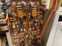
The voltage on the source of each fet is 11.6V on each channel. The traces on the back side of the board where the fets are starting to protest all of the heat they’ve been subjected to so I put in a couple of transistor sockets.
Dan
Attachments
Fet source = 11.6Vdc check. Fet current is near total cutoff (Rd = 10k), so Fet gate is (minus some 2Vdc), at 9.6Vdc. R702-R705 midpoint is at +15.8Vdc whatever. Loss over R719 (1Meg) is 6.2V??? -> Current through R719 = 6.2µA??? Through the gate of TR701? Through C701? How?
What's the gate voltage?What are the real values of R702 & R705? Both channels! I'm baffled...
What's the gate voltage?What are the real values of R702 & R705? Both channels! I'm baffled...
Fet source = 11.6Vdc check. Fet current is near total cutoff (Rd = 10k), so Fet gate is (minus some 2Vdc), at 9.6Vdc. R702-R705 midpoint is at +15.8Vdc whatever. Loss over R719 (1Meg) is 6.2V??? -> Current through R719 = 6.2µA??? Through the gate of TR701? Through C701? How?
What's the gate voltage?What are the real values of R702 & R705? Both channels! I'm baffled...
Haha it’s more of a puzzle to me than you, seeing most of this is over my head. The gate voltage on TR702 is 9.82V and on TR701 is 9.96V.
R701 is measuring 1001 ohms and R702 is measuring 988 ohms
As fo R705 and R706, I’m measuring them in circuit as it’s a pain to get to the backside. If you really want me to measure them out of circuit I will, but each are measuring at 30kohm. I assume the circuit is altering the measurement, it isn’t likely that both would drift from 47kohm to 30kohm equally.
Dan
Thank you so much you guys for help on sourcing parts. I’ll grab some of the K30As, with nobody else stocking them is there any chance they may be fakes?
Dan[/QUOTE]
hi Dan, Ive bought parts from them before, the ones ive tested/matched seemed genuine, including jfets. I think they get end of line stuff, like they may get the N channel, but not P. Many people on DIYA have used them and dont recall any complaints.
Dan[/QUOTE]
hi Dan, Ive bought parts from them before, the ones ive tested/matched seemed genuine, including jfets. I think they get end of line stuff, like they may get the N channel, but not P. Many people on DIYA have used them and dont recall any complaints.
My assumption that the fet's are close to pinch off is right: Vgs = 1.8 and 1.6V.The gate voltage on TR702 is 9.82V and on TR701 is 9.96V.
These are not relevant in the dc-calculations (unless C701 is leaking); thanks anyhow.R701 is measuring 1001 ohms and R702 is measuring 988 ohms
In circuit measurement includes many other parts, in this case R703 and R705 in parallel (100k//47k=32k), routing is via the supply. What voltage is on that node between R703 and R705?As fo R705 and R706, I’m measuring them in circuit ... but each are measuring at 30kohm. I assume the circuit is altering the measurement...
With a Vs of +11.6Vdc and R723 at 19.1Vdc, the calculations go nuts when I try to close the circle. As if current is evaporating somewhere...
One more: can you measure all the voltages on the the three legs of all the semi's? And the rail is really +49.2Vdc (it is a single supply rail amp)?
- Home
- Amplifiers
- Solid State
- Need to replace 2SK30A on tone board of Sansui AU-9500, 2SK170???