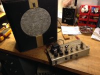
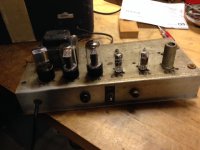
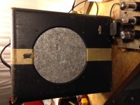
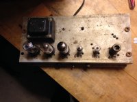
I'm looking for a schematic for this amp. It doesn't use the normal tubes except for output stage. It uses 6C4(2), 6AT6, 6V6(2), 6X5. Sound familiar to anyone? I'll send pics if needed.
I have no idea, I just know a lot of the gretsch schematics I have access to are for model numbers of that format.
Yes I agree. Most of schematics I have seen do not use the tubes i see in this chassis. I will try and post pics.
For guidance ONLY.
the 6C4 is VERY much like 1/2 a 12AU7 dual triode
the 6AT6 is VERY much like 1/2 a 12AT7 dual triode. The diode plates will almost certainly be left unconnected.
You should be able to find both with some effort but both are approaching rocking horse poo availability.
Cheers,
Ian
the 6C4 is VERY much like 1/2 a 12AU7 dual triode
the 6AT6 is VERY much like 1/2 a 12AT7 dual triode. The diode plates will almost certainly be left unconnected.
You should be able to find both with some effort but both are approaching rocking horse poo availability.
Cheers,
Ian
I have some other resources I will explore at the shop, but in the mean time, this is not a complex amp. You could sit down with paper and pencil and draw up a schematic from the circuit.
Judging from the tubes, the power supply will hold no surprises. The pair of outputs suggests push pull, but you can easily determine if it is single ended parallel tubes. Either way, the circuit will be conventional. I'd wager the triode next to them is a split load phase inverter.
That leaves a couple triodes for preamp stages.
I do this all the time for old amps I cannot find documents for. it isn't hard.
This may be a bad lead BUT
I have seen forum posts which suggest that all Gretsch Amps up untill 1968 were actually built by Valco who also did National and Supro Amps.
A search of Valco or Supro schematics may turn up something.
Cheers,
Ian
I have seen forum posts which suggest that all Gretsch Amps up untill 1968 were actually built by Valco who also did National and Supro Amps.
A search of Valco or Supro schematics may turn up something.
Cheers,
Ian
Yes, and you may also note a lot of the Valco and other amps also use the 6xxx numbers in the model designations.
There are a lot of old schematics here.
Guitar Amplifier Schematics and more
I looked through the gretsch ones, nothing like yours, I did not peruse the Valco section farther down. You might scroll down to Valco and go through them to see if any match you. it isn't a complete collection, but it has quite a few. Good place to start anyway.
Ok so I have been playing around with this on the bench some more. This is what I think I know. I'm not sure that it is the original amp in this unit. When I power it up there is just alot of noise. Hissing, popping but not low frequency like ground issues. I have replaced all the resisters and the frontend tubes but none of that made a difference. If I short the input to ground noise reduces just barely not much difference. If I pull the 1st stage tube all the noise goes away. If I keep it in and ground the out from 1st stage to 2nd stage amp is very quiet. Again this is with new tubes. I will post the schematic of 1st and 2nd stage. It uses some resister values that seem very high to me. Also wondering why they use a low mu for 1st stage and then High mu for 2nd. Anyway seems like issues are in the 1st stage to me. Appreciate any opinions.
Attachments
So apply a signal to the input, and see if it appears on the plate of the first tube. If so, then does it appear on the plate of the second tube? Do both plates have B+ on them? Your 15 meg grid resistors and grounded cathode tell us the two stages are "grid leak" biased. it may be difficult for your meter, but check that they are not open.
430k is a non-standard value these days. But noisy plate resistors can make a stage noisy. And check their value.
430k is a non-standard value these days. But noisy plate resistors can make a stage noisy. And check their value.
All of the resistors are brand new and were replaced by me. The tubes are new also. I will check the Plate voltages and look at them with a scope. I do believe that signal is at the plates. You can play a guitar through the amp but it is distorted and very noisy. Does the fact that I pull the 1st stage tube and the amp gets very quiet mean that is the problem with that stage. I was thinking about pulling 1st tube and injecting signal into grid of second stage and see if sounds quiet but still hear the signal amplified. Anyway i'll get measurements and post.
Thanks
Thanks
With a 15M Grid Leak for Grid Leak Bias of the Input Tube you may well have a problem.
Grid Leak Bias will NOT work with an old gassy tube.
This is because the negative grid current from the gas ionization opposes the positive grid current needed to establish the grid leak bias.
Even though you have a new tube it maybe gassy. Do you have another to try?
The plate voltage will tell you if it is OK. It should be between 1/2 and 2/3 of the B+ voltage at the top of the 430K anode load resistor.
If the plate voltage is significantly less than 1/2 B+ then the tube is no good in this circuit.
Cheers,
Ian
Last edited:
Ok so I have done some more work with this amp. I discovered that one side of my output transformer was open and I replaced that. That took care of most of the distortion i was hearing. Almost all of the noise is gone from the first stage now. I don't think it had anything to do with the XFMR though. New input cable and jack probably. Reading Gingertube post I believe that I have the problem he is talking about. The first stage tube has 20vdc measured at the plate and ~200vdc across the plate supply resister of 430K. Can the tube operate correctly at this plate voltage!? This is a NOS tube that was just purchased and test well on my tester. The older tube I replaced shows the same voltage at the plate. I have thought about changing the design of the first stage to a simple RC coupled amp from the RCA tube manual. I have to say though that the amp seems to work ok now. A little bit of hum but acceptable. Any thoughts??
20 V DC on the anode is not enough. Try changing that 15Meg grid leak resistor, take it down to 5M6 for start and see if that reduces tube current enough to get the anode voltage up.
Also check the anode load resistor to make sure it has not gone ridiculously high in resistance.
Other thing which could cause low anode volts is a leaky coupling cap to the next stage. Check that too. If this is the case then the anode voltage will be low even with the tube pulled, so that is a way to check, with no tube there should be no voltage drop across the anode load resistor.
Actually do these 2 checks first before changing the grid leak resistor.
Cheers,
Ian
Last edited:
ok pulled the input tube and the plate voltage goes up to a little over 200vdc. Plate load resistor is 430K and brand new so are all the caps in system. Changed grid leak resistor to 5M and measured plate voltage at 18vdc. The only thing that gets voltage up is to lower the plate load resistor. I put 100k in parallel with the 430k and plate goes to 33vdc. Note that playing guitar through system seems to work ok. I cant hear any difference between lower voltage and the higher plate voltage. Maybe I shouldnt worry.
- Status
- Not open for further replies.
- Home
- Live Sound
- Instruments and Amps
- Need Schematic for Gretsch Artist Model


