I want to build a line level crossover for my biamped system. I would like to do a vacuum tube version some day but I currently have no tube parts and lots of sand so I am looking at an emitter follower based version of the S-K tube circuit as shown on Steve Bench's website. As a quick sanity check I diddled with some of his values in the hopes of making it more transistor friendly.
What I am considering is something like that shown below. for the LP portion. No doubt many of the values are sub optimum since I have not learned the theory of how the circuit works but this was close enough that it simmed OK and gave the expected curve.
What I need is a site with a good clear explanation and derivation of this type of filter so that I can do it correctly. It also occurs to me that if I understood the circuit properly I could move one of the poles down in frequency so that I can have a first order rolloff from about 50Hz up to the desired crossover frequency of 180Hz where the other two poles would kick in. This would be to compensate for baffle loses in this OB system.
Does anyone know of such a site (or want to tackle it personally 😉 )?
mike
Attachments
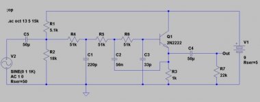
In trying to analyze this I pulled out the old linear circuit theory book and tried to plow through. I was attempting to apply node analysis to it but I could not figure out how to handle the transistor. It seems that it shouldn't be necessary to use the transistor equivalent circuit since in an AC sense all it is doing is holding the voltage at the emitter to the same values as that at the base (just offset by the DC BE junction forward bias voltage).
All that said I still can't figure out what to do. In normal node analysis I would need to specify the current into the base of the transistor in terms of node voltages and I don't know how to do that (or avoid the necessity of it).
Should I just ignore the transistor and analyze the circuit with R6 in parallel with C2 and R3 in parallel with C3 (with output voltage taken between those parallel pairs)?
And on a completely different subject... if I decide to include power amplification in the form of a chip amp would I be able to include some of the filtering in the actual circuit around the chip amp since it is essentially a high current opamp or is it better to do all the filtering with low level components (trans or opamps) and use the chip amp only for straight power amplification?
mike
- Status
- Not open for further replies.