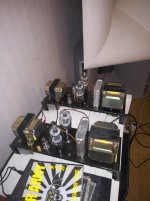
Good evening. I finally have my 807 PP class A2 monoblocks operational. They started out as an attempt to build something useful from a pair of old Philips EL6400 PA amps, several iterations later they have evolved into something completely different using only the same mains and output transformers.
The circuit is somewhat inspired by Altec 1570, where the output tubes are driven by a pair of cathode followers loaded by a center tapped choke. Where Altec used a two 6W6s to push a pair of 811s, I got away with using the smaller pentode sections of ECL84/6DX8 to drive my 807 deep into class A2. The triode sections (~1/2 12AT7) are used as an LTP input stage.
Please ignore the abscense of grid stoppers, protection diodes and even screen grids in the conceptual schematic, they're all there IRL. And while you're at it, please have mercy with my photography skills too... And yeah, I'll definitely get insulated top caps.
At the moment I'm running these amps with zero NFB (the output tubes are triode wired) with an open loop gain of x10, but I feel I could trade some gain against higher DF.
GNFB from the output to the unused input of the LTP would be the most obvious method, but perhaps we can come up with something more exiting?
Some kind of symmetrical feedback either from the 807 plates or the unused UL (50%) taps would be nice, though I'm aware that "Schade" feedback supposedly don't work well with triode input stages.
Perhaps changing the input stages to cascoded LTPs would make them more suitable for local feedback?
Attachments

That unused LPT input is begging for feedback at least a modest amount. Beyond that more gain may be required.
You can get some ideas from my design:
https://www.diyaudio.com/community/threads/push-pull-807-amplifier-without-global-nfb.384100/
It has cascoded LTP input, cathode follower driver stage, UL PP 807 output, 12dB GNFB (don't believe the topic title), also local cathode feedback.
Be prepared it will sound totally different than without global negative feedback.
P.S. baudouin0 helped me a lot with his advices.
baudouin0: I fully agree that the unused LTP input is the "prime suspect" for NFB and that's probably how I will end up doing it, I just can't resist doing a bit of brainstorming on the topic of alternative NFB methods 🙂
Icsaszar: That's one nice amp you have there!
Cascoding the LTP would probably be a game changer here. Unfortunately I'm already low on both heater winding current capacity and B+ so adding more tubes is not an option. Fets on the other hand don't have heaters, so I guess I could either put a pair of high voltage mosfets "above" the input triodes to get a cascode OR insert a pair of Jfets "below" the triodes, with proper bias arrangments in both cases of course. The latter case feels a bit more experimental and my gut feeling tells me that this might lead to some very high gain numbers?
Yes you can put jfets below the triodes just bias the grids up a bit and used a CCS as a tail. You will end up with quite a lot of gain. I used 2sk170 but they will be too high gain/low current for your needs. The fets need to be matched and you may want a trim pot. Adding source resistors will drop the gain.
baudouin0: That is an interesting schematic. I have a bag of J310 Jfets somewhere, I think they have lower gm than 2SK170 and should result in less excessive gain.
I'm also considering output plate to input cathode feedback (probably messes upp the phase splitting) or output plate to input grid feedback (messes up the input impedance...).
I'm also considering output plate to input cathode feedback (probably messes upp the phase splitting) or output plate to input grid feedback (messes up the input impedance...).
Based on the description in post #1, I conclude that the conceptual schematic is wrong in that it shows the pentode sections of the ECL84's as the first stage, and the triode sections as the driver stage.
What is the value of the plate resistors in the first stage?
What is the value of the plate resistors in the first stage?
Kwadjo: Perhaps the schematic is a bit too simplified: The triode sections make up the input LTP (with 47k plate resistors), while the pentodes operate as triode wired cathode followers.
In an earlier version the cathode followers were operating in pentode mode with bootstrap caps from the cathodes to the screen grids but for some very stupid reasons* I had ro rebuild the whole input/driver section several times and somewhere along the way I found that they work just as fine in triode mode.
* I could swear that my first prototype in the original EL6400 chassis worked just fine with a pair of Edcor 10k/600 ohms 1W OPTs as cathode chokes. After building the real version in new chassis I suddenly got problems with ugly distortion at high frequencies once I got over 1W or so. I blamed oscillations so I changed the layout and tried different tube types several times before I realized it was all in the chokes/transformers...😵
- Home
- Amplifiers
- Tubes / Valves
- Need ideas re. local feedback in old school PP amp.