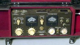
I have two of these Auricon NR25 amps. They are very attractively made. The original purpose was to convert a microphone (and a line) input into a strong enough signal to drive a "galvo" (a coil driven mirror) to "write" an optical sound track on film, in the "variable density format." This last, I do not have a use for.
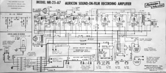
But it has a headphone output also and I want to use them as mic amps only. As an audio circuit it has some funky features. In particular the first and second (L to R) 3V4 pentodes are for "noise reduction" (the "NR" in the name). Those apparently make sure that unused portions of the optical track are "blacked out" to prevent light leakage. As you will notice they form a separate circuit, with its own batteries. The amp will work without them.
Now this amp has certain frequency "corrections" as the galvo peaks around 5kHz and drops thereafter. I would like to eliminate them as they affect the headphone output also. My question is, can someone tell me what is eq and what just feedback loop? For instance the L/C network around the "K-1909" coil seems like a hi-cut. Can I bypass it?
Any help would be endlessly appreciated.
Attachments
What a delightful device. The obsolete tube types, the use of "B" and "A" batteries for field use, all take one back to a time just after camaras were cranked by hand. It is interesting that there were suppliers other than RCA and Western Electric, the two large corporations usually credited on screen. One of my neighbors bought a 1935 van truck once painted up for Western Electric. Great Hulking thing, probably longer and taller than a current Ford E350 15 passenger van, but the windows were only in the back.
Due to the extensive use of transformers as stage coupling and output devices, I doubt this will ever be a 20-20000 hz device. However you can fiddle with changing the coupling capacitors and feedback capacitors. Modern capacitors are much cheaper than they were in 1930. AC resistance of a series RC pair is proportional to 1/sqrt(2pi*F*R*C) where C is in farads, R is in ohms and F is in cycles per second. .01 microfarad=10e-8 farad.
I would expect limited upper frequency range is important when using a galvanometer as the transducer.
It also might be difficult to find an earphone at 2500 ohms, though these used to be common.
Last edited:
i can't believe it! There was one such 16mm camera in the closet in my film school. This camera could record audio right on the negative!! Pretty unique feature, normal workflow is to have a separate tape recorder. I wonder if this contraption was for that camera or a standalone one.
That K-1909 circuit could be a high cut but also could be giving a boost at 5kHz depending on Q and LC values. You could try shorting the inductor but you may need to also lift the cap after it that goes to ground or put a somewhat smaller cap in its place or risk losing treble. It's difficult to read the values in this part of the circuit.
It is probably for the camera, among others. It comes in a case with its batteries, etc., but in old pictures people carry this and camera together. There is also a separate gadget to burn the final (optical) soundtrack to film, which also uses this amp.
The whole amp has only six capacitors. This (the 0.0004mF) seems to be the only one that is part of an identifiable LC network. There are two others after the second tube/valve but those are for a "tone control" which I want to keep.
Thanks for your input. I should just bypass the coil and disconnect the 0.0004mF and see what happens, unlikely to cause much harm.
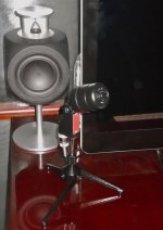
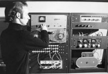
If you see anything else, I will appreciate. I am attaching a picture of the device (as I received it) and of its microphone (post-restoration, really a badge engineered E-V 635).
Thanks for your input. I should just bypass the coil and disconnect the 0.0004mF and see what happens, unlikely to cause much harm.
If you see anything else, I will appreciate. I am attaching a picture of the device (as I received it) and of its microphone (post-restoration, really a badge engineered E-V 635).
Attachments
I really don't think that this would be a good candidate for a high quality microphone preamp.
The microphone input transformer was designed for a 50 ohm microphone.
The coupling capacitors won't pass low frequencies.
I believe that this recording amplifier was designed to record dialog on an optical 16mm film soundtrack. As such, it purposely has a limited frequency response. Probably 100Hz to 5kHz.
The first two 3V4 tubes drive a volume level indicator. The third 3V4 drives the 2.5k headphone output. I don't see anything in the schematic that would reduce the noise.
Due to the extensive use of transformers as stage coupling and output devices, I doubt this will ever be a 20-20000 Hz device. However you can fiddle with changing the coupling capacitors and feedback capacitors.
It also might be difficult to find an earphone at 2500 ohms, though these used to be common.
I have no expectations of "high quality" -- just want to remove any deliberate limitations put in for the original purpose. The transformers are mostly potted devices, not sure if this indicates any better quality. Actually the headphone transformer is the only one that is not, and I thought I might replace that with something of lower output impedance. The literature says, "it is optimized for the 'latest' stethoscope-style earphones!"
The first two 3V4 tubes drive a volume level indicator. The third 3V4 drives the 2.5k headphone output. I don't see anything in the schematic that would reduce the noise.
It is not "noise reduction" in the sense we know it now. See attached from the manual. I am yet to figure out what this means or how it works.
Attachments
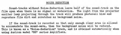
What the noise reduction does is not have a projected light "Bias." In the even older version zero signal (I.E. half of the final sound track area at 50% modulation) was Clear final film. That would create noise on the projection playback from any dirt or scratches on the film. By using Black as the no signal the playback would have less noise.
What the noise reduction does is not have a projected light "Bias." In the even older version zero signal (I.E. half of the final sound track area at 50% modulation) was Clear final film. That would create noise on the projection playback from any dirt or scratches on the film. By using Black as the no signal the playback would have less noise.
So I thought, from everything I read, that Auricon used "variable density," not variable area, looks like I was wrong. Now I understand it even less: do you mean, rather than 50-50, with no signal, the entire track is black? Why would the system not be just designed that way, rather than this "NR" system? A photocell will not read a -tive values anyways, so an all black track opening with increasing volume? At the loudest bits, with the track wide clear, any scratches would probably be masked.
There is a wonderful Encyclopedia Brittanica film on Youtube about this. There were three systems used; var density, one sided var area and symmetrical var area. The same projector played back all three.
i can't believe it! There was one such 16mm camera in the closet in my film school. This camera could record audio right on the negative!! Pretty unique feature, normal workflow is to have a separate tape recorder. I wonder if this contraption was for that camera or a standalone one.
I think this was the complete Auricon sound set-up. The device on the lower right hand transfers sound to film. My amp is the one right above that.
Attachments
Any system that modulates the amount of light reaching the projectors photocell will have the same results. The better the system the less noise... of course. With a variable density system the noise level is higher than a variable area system that uses all black as zero signal.
The unit you have is intended to drive a voice coil actuator with a permanent magnet for variable area recording. The lamp intensity is controlled by a rheostat fed by 12 volts.
With no signal it is all black, as the signal increases this system moves the 0 value to enough light to allow just full scale excursion, no more. So if the peak level of the signal is only 10% of full scale then it will only modulate from black to 10% open area. As the level rises to 100% modulation, it will eventually use all of the area.
Open or clear area is noisier due to dirt, scratches and the nature of the photocells used. Without any light they were quieter than when exposed to light. So these guys came up with a system of noise reduction that varies the area in use to match the peak signal level.
Last edited:
The mic transformer can be easily measured for step-up ratio, and nominal bandwidth response using matched resistive loading. If it is in a mu-metal screened can then it may have good use for phono.
- Status
- Not open for further replies.
- Home
- Live Sound
- Instruments and Amps
- Need help with old mic amp