I'm attempting to design a single sided PCB for a IRS2092 based class D amp with +/- 60V power supply Ive already made the power supply and protection circuits and only have the amp pcb's left to make, I've heard that this chip is very sensitive to layouts, so I uploaded my eagle cad files and pdfs of the circuit layouts and would really appreciate if I could have some assistance on improving the layout or some of the circuit values, I just don't want it to blow up the first time I build it 😀. Its only for 4 ohm subwoofers so the switching frequency can be low. I need a little help selecting the deadtime and over current protection resistors. the FET I'm using it the FQA27N25, the 22uh inductor and 1uf film cap is going to be on a separate board above the switching mosfets thats why its not on the schematic yet, I'm going to wrap the inductor board in copper foil tape to reduce interference. any help would really be appreciated, thanks. Sorry for the messy eagle cad layout.
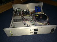
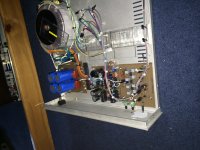
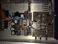
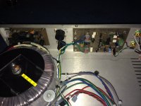
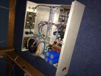
Inside the chassis now is the protection board (mosfet relay based), the soft start using MOV's, the capacitor bank and rectifiers, low current power supply (+/- 15V and 12V for the bias, and the 24db 100Hz low pass filter.
Inside the chassis now is the protection board (mosfet relay based), the soft start using MOV's, the capacitor bank and rectifiers, low current power supply (+/- 15V and 12V for the bias, and the 24db 100Hz low pass filter.
Attachments
Last edited:


The 2092 should be decoupled as close to its power pins as possible.
The whole layout should be as short and as tight as possible.
The output mosfets needs decoupling right next to the pins.
Your output mosfets look like they have too much gate capacitance 50nC,
I would use irfb4019 or irfb4020 which are about 20nC.
If you want to use higher power mosfets then you will probably need gate buffers, either npn/pnp or TC4420.
I always use max dead time to keep mosfets cool.
The over current protect needs adjusting to stop resetting at full power but at the same time protect against shorts.
- Status
- Not open for further replies.