Hi,
As stated, I need advice on grounding strategy for a modular DAC project I'm working on. Let me explain.
Say we have a DAC board, a closely connected I/V board, a power supply board, a digital inputs board and a uController board in a metal enclosure. What would be the best way of connecting those components ground and noise wise?
I was thinking of providing separate ground wires for each of the modules at the power entry point of said modules to a common "star ground" and from there to the power entry/filter module's ground connector. Of course the enclosure would be grounded too. Matter of safety as I have red.
Any thoughts and help would be appreciated.
Best regards, Kovaxant
Hi it would help if you post a drawing of all boards in the enclosure (or the assumed positions of them).
It would also be good to check if all digital sources have SPDIF transformers for galvanic separation. Despite the better waveform without transformers the galvanic separation counts with todays SBC sources IMHO.
Secondary side of a PSU has GND or Audio GND. Mains side of things has Protective Earth or PE and it would be better no to speak of "grounding" as these matters are complicated enough to most and as a result of that they are mixed up often. Ground/GND is NOT PE and thus they are not necessarily connected.... The casing must be connected to PE as an absolute minimum safety measure. Then the challenge starts...
Example: when the sources AND the DACs input boards would lack SPDIF transformers AND one connects Audio GND to PE directly in the DAC then one would have created a very nice ground loop.
Last edited:
DAC in an enclosure
Hi,
Thanks for a quick response.
Here is attached my vision of modules in an enclosure. The I/V stage is directly below the DAC board.
Yes, galvanic isolation has been incorporated in the digital inputs board (Murata transformers).
Cheers, Kovaxant
Hi,
Thanks for a quick response.
Here is attached my vision of modules in an enclosure. The I/V stage is directly below the DAC board.
Yes, galvanic isolation has been incorporated in the digital inputs board (Murata transformers).
Cheers, Kovaxant
Attachments
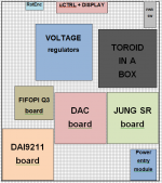
Where are the connections located (=on the boards)? For a start I would have analog stuff located at the utmost right side of the device and digital in the middle. Analog should be kept as far away as possible from digital, microcontroller, display and mains related stuff. So swapping the DAI9211 and the DAC board.
Last edited:
A comprehensive grounding diagram should also show connections externally of grounds, especially on single-ended audio ins/outs.
Even with isolating transformers, grounds can get corrupted by HF noise currents from digital sources so don't assume isolation at DC deals with all the issues.
@J-P I wasn't talking particularly about you. Hey - but if the cap fits.....
Even with isolating transformers, grounds can get corrupted by HF noise currents from digital sources so don't assume isolation at DC deals with all the issues.
@J-P I wasn't talking particularly about you. Hey - but if the cap fits.....
Last edited:
Hi, I don't assume anything, that is why I asked for a drawing and the connections 🙂 It is also still hard to judge from a drawing, pictures of the PCBs would be better I guess. Grounding/PE and all their peculiarities are already not the easiest and working from a screen and not seeing the real device will make things complicated.
Last edited:
Separate digital GND wires from analog GND wires and connect them together either on the voltage regulators PCB or on the DAC board (like a star GND).
Thank you guys for your advice. Star ground at the psu board will be explored, I'll see how it behaves.
Cheers, Kovaxant
Cheers, Kovaxant
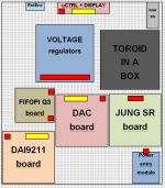
I agree. That does look much better. I would have to redesign the back plate of the enclosure, but it's NP. The thing that worries me is the FIFOPI Q3 position. Will look into if it can be oriented / fitted properly concerning the I2S signal cables length to the DAC board.
J-P, thank you kindly for your work and time invested.
Cheers
J-P, thank you kindly for your work and time invested.
Cheers
- Home
- Source & Line
- Digital Line Level
- Need advice on grounding strategy for a modular DAC